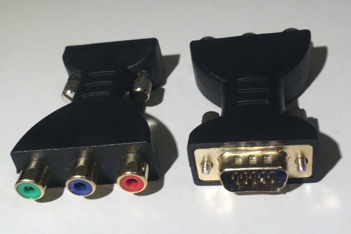
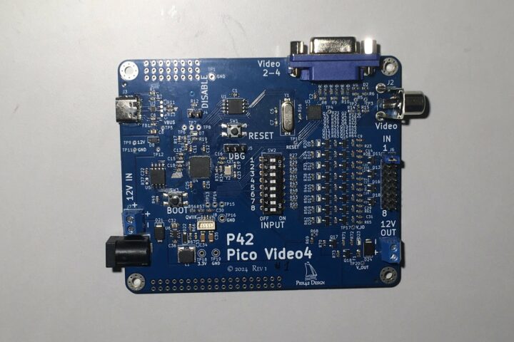
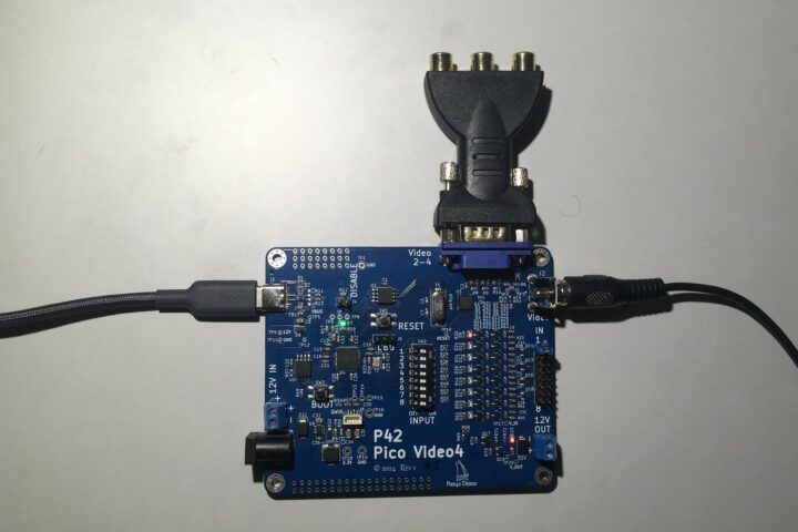
The Pico Video4 Display is a Raspberry Pi RP2040-powered board that supports up to 4 analog composite video display interfaces with dedicated frame buffer memory accessible via SPI. The four video outputs are sent out through an RCA connector and a VGA DB15-HD connector that uses the red, green, and blue channels to create a composite video signal.
The Pico Video4 Display is based on the Raspberry Pi RP2040 microcontroller chip and the VLSI VS23S040 four-megabit static RAM device with a video display controller that can output NTSC, PAL, and VGA video from the memory array. It provides the composite video outputs with a dedicated frame buffer and other hardware. This ensures that the RP2040’s limited processing power and memory are not hogged up in generating the video signal, leaving room for other major tasks.
It has 8 inputs that are voltage-compatible to the input voltage, from 5V to 12 V, and 8 dip switches to simulate the inputs. There is a 16-megabit SPI flash memory chip on board that is preloaded with a 94-character bitmap, a bouncing ball demo, and 9 demo images. Two I/O pins of the VLSI VS23S040 chip are wired to the horizontal and vertical sync pins of the VGA connector to enable an experimental VGA display in the future.
The Video4 builds on Pier 42’s previous projects: Arduino NTSC/PAL Video Display Shield and the VGA Shield Wing. It supports multiple resolutions and enables you to use your old displays in new projects.
Pico Video4 Display specification:
- Microcontroller – Raspberry Pi RP2040 dual Cortex M0+ cores MCU up to 133 MHz with 264 kB of embedded SRAM
- SPI chip – VLSI VS23S040 chip with an 8-bit parallel interface and an integrated video display controller
- Storage – 16Mbit program flash memory
- Video
- 4x composite video outputs via a RCA connector and a VGA DB15-HD connector
- Supported resolutions – NTSC 320×200 or 426×200 with 256 colors and PAL 300×240 or 500×240 with 256 colors
- Crystal oscillator frequencies – NTSC 3.579545 MHz or PAL 4.43618 MHz
- Communication interface – SPI up to 38 MHz
- Video Frame Buffer – 4x 1 Mbit (4x 125 KB)
- USB – 1x USB-C connector for 5V power and programming
- Expansion – 8x high-voltage inputs compatible with the input voltage, and 8 dip switches to simulate the inputs
- Debugging – SWD Debug interface
- Misc – LED and 2-pin jumper for status and control, Reset and Boot buttons, TH prototyping area
- Power Supply
- 5V DC from USB and up to 12V DC from the barrel connector or screw terminal
- 12V power output via screw terminal, switched and fused with 500mA polyfuse
- Dimensions – 100 x 85mm
The Video4 Display board is similar to other RP2040 devices with HDMI/DVI or VGA video outputs like the Adafruit Feather RP2040, Olimex RP2040-PICO-PC, Waveshare RP2040-PiZero, Pimoroni Pico VGA Demo Base board, and the Olimex NEO6502.

Like other Pico boards, you can program the Pico Video4 Display board using C/C++ or MicroPython. Hardware schematics, documentation, and other resources are hosted in the project’s GitHub repository. The board is currently available on Tindie for $42, with the VGA-to-RCA adapter sold separately for $5.

Tomisin is a writer specializing in hardware product reviews, comparisons, and explainers. He is very passionate about small form factor and single-board computers.
Support CNX Software! Donate via cryptocurrencies, become a Patron on Patreon, or purchase goods on Amazon or Aliexpress


