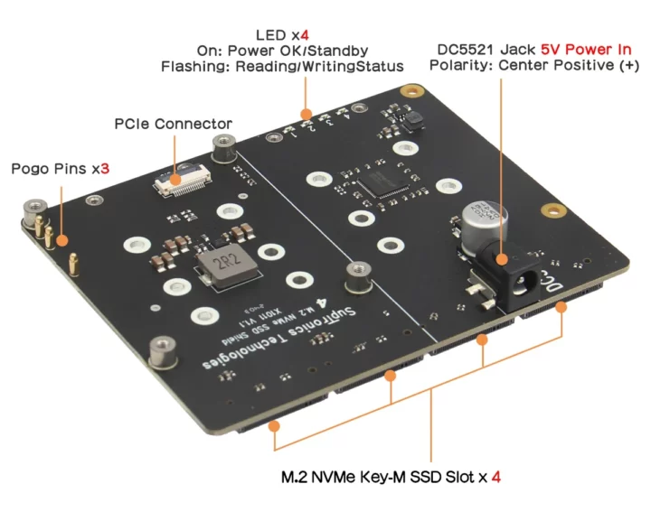
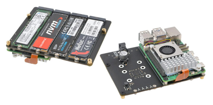
Geekworm X1011 is a new expansion board for the Raspberry Pi 5 with four M.2 sockets enabling the insertion of up to four M.2 NVMe SSDs with data pushed through the PCIe Gen2 interface of the popular SBC.
We were already wondering why most people would want to connect two NVMe SSDs to the Raspberry Pi 5 when the Geekworm X1004 HAT+ was launched considering the 5GT/s limitation from the board and the PCIe switch, but the company decided to double the number of drives with the X1011 meaning each drive can achieve up to around 100 MB/s (or 400MB/s) when used simultaneously. It does look nice and fairly compact though.
Geekworm X1011 specifications:
- Supported SBC – Raspberry Pi 5 and other SBCs with a compatible 16-pin PCIe FPC connector and mounting holes
- Chipset – ASMedia ASM1184e PCI express packet switch with 1x PCIe Gen2 x1 upstream port and 4x PCIe Gen2 x1 downstream ports
- 4x M.2 sockets for up to 16TB storage capacity (4x 4TB) with M.2 NVMe 2280/2260/2242/2230 SSDs (SATA not supported)
- Max data transfers – Up to 5 Gbps PCIe 2.0
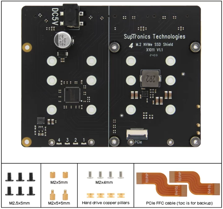
- Host interface – Raspberry Pi 5 PCIe FFC connector (37mm FFC cable provided)
- Note – NVMe boot is not supported because the Raspberry Pi firmware does not currently support PCIe switches.
- Power Management
- 5V/5A DC via FFC & pogo pins (using the USB-C port on the Pi 5)
- 5V/5A DC via 5.5/2.1mm DC power jack
- DC/DC step-down converter delivering a maximum of 10A to power the SSDs
- Compatible with the HAT+ standby power state, automatically turning off when the Raspberry Pi 5 shuts down.
- Important: Do not power the Raspberry Pi 5 through its USB-C port at the same time if you are using the DC jack.
- Dimensions – 109 x 87.2mm


While the Raspberry Pi 5’s PCIe interface could be configured up to switch to PCIe Gen 3 x1, this won’t help because the PCIe switch only supports PCIe Gen 2 x1. That means we are left with a solution that delivers about the same sequential read/write performance as SATA hard drives, albeit in a much smaller form factor and random I/Os will still be considerably faster. A wiki has been set up with more technical details and instructions to get started.
Jeff Geerling got a sample and confirmed the performance. He also compared it to the Rockchip RK3588-powered FriendlyELEC CM3588 NAS Kit which is about $20 more expensive for a complete system, but with a PCIe Gen3 x4 interface (PCIe Gen3 x1 (8GT/s) per socket) that delivers much better performance and a 2.5GbE port that can push 2.5 times more data to the network than the gigabit Ethernet on the Raspberry Pi 5. None of these support SATA drives, and if you prefer this type of drive, the Radxa Penta SATA HAT provides a viable option to build a NAS for the Raspberry Pi 5.
The Geekworm X1011 expansion board ships with two PCIe FFC cables (one is a spare), various screws, spacers, and nuts. It can be purchased on Geekworm for $51, on Aliexpress for $50, and might soon be found on the company’s Amazon store.

Jean-Luc started CNX Software in 2010 as a part-time endeavor, before quitting his job as a software engineering manager, and starting to write daily news, and reviews full time later in 2011.
Support CNX Software! Donate via cryptocurrencies, become a Patron on Patreon, or purchase goods on Amazon or Aliexpress


> We were already wondering why most people would want to connect two NVMe SSDs to the Raspberry Pi 5
Because they need RAID 1?
software – for nvme? how many nvme have failed you so far?
No!, because they need RAID 0. 🙂
Behind that nice ‘single Gen2 PCIe lane’ bottleneck?
behind gigabit lan bottleneck?
but you could use another m.2 devices there like 2.5G network
Nice shield or HAT but I quite don’t understand their numbers.
If I take quite common SSD PM981 1TB NVMe, it has power requirement on the sticker 3.3V 2.8A. This drive does not draw a maximum of 3.3V*2.8A=9.24W all the time, but you should always count on the worst-case scenario when designing power source circuits.These four SSD drivers can demand up to 36.96W. Could somebody explain to me how it would go with the 25W maximum power input? I am not smart enough to understand this.
Simply put, it doesn’t.
But it’s a simple bet that four of those aren’t going to have a power burst at the same time, specially when they are all limited to a single lane of PCIe 2.0.
Running at 2.0 speeds probably make it much easier on the SSD controller as they are designed to handle 3.0 x4. Nevermind that all four of them share that lane, so it’s very likely that they will never get hit by a request burst at the same time.
There is also a filtering capacitor for what is worth, that might be able to absorb some very very small burst(e.g. in the order of 1 ms).
It might work but I rather put my hands off everything demanding low voltage and high current. I would rather see this board using 12V.
For $50, I am sorry, it is too much for such a creepy design.
That’s a good point. If you’re going to put an external power jack on the board along with the SMPS to convert to 3.3V, you might as well use 12V (or better yet 19V) to keep the currents down. Using 5V for that seems like you’re just moving the problem a further down the road.
Anyone keeping a list of SBC’s using compatible 16-pin PCIe FPC?
LOL
It’s pretty short right now:
I can only think about the Kaki Pi: https://www.cnx-software.com/2024/03/05/kaki-pi-raspberry-pi-inspired-renesas-rz-v2h-ai-sbc-with-four-camera-connectors-pcie-3-0/, but I think there’s at least another one.
> I can only think about the Kaki Pi
The different connector position might limit compatibility with certain PCIe HATs. Radxa did it better with Rock 5C since they put the FPC connector in the exact same position.