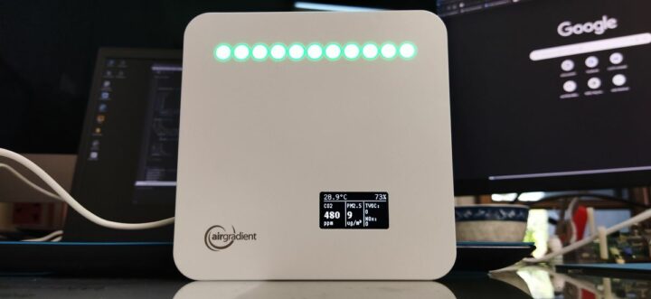
The product we are reviewing today is the “AirGradient ONE” air quality monitor kit which is an updated version of the earlier AirGradient air quality monitor. The device is equipped with sensors from Sensirion and Plantower, allowing it to measure many air quality parameters such as CO2, PM2.5, TVOCs, NOx, temperature, and humidity. It is an indoor air quality monitor that is both open-source software and open hardware. This means that the Arduino source code, schematic diagrams, PCB, and 3D models of the enclosure are available to developers.
AirGradient ONE DIY Kit Unboxing
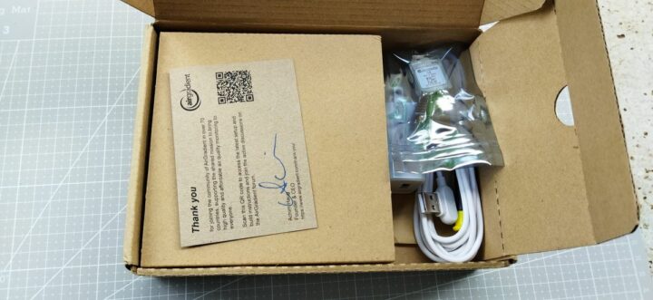
The device was packaged within a cardboard box, with a greeting card from the manufacturer. The card features a QR code linking to a webpage with the installation guide.
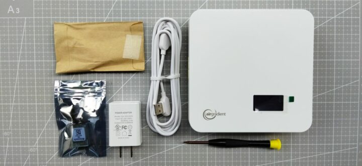
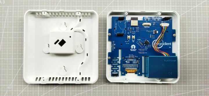
Since I requested the Kit version (there’s also a fully assembled model), some sensors were not pre-assembled and they were well-packaged in separate seals. The main PCB was already inside the enclosure, with the screws had not yet been fastened. Additional components in the box included a screwdriver, screws, a USB Type-C cable, and a 5V 2A adapter.
Specifications
This kit is the AirGradient ONE using PCB V9 featuring the ESP32-C3 Mini as the main microcontroller. Additionally, it includes a 1.3-inch OLED display with a resolution of 128×64 pixels. The mainboard is also equipped with 11 programmable NeoPixel RGB LEDs that are used to visualize the air quality level. The details of the other components inside the packages are listed below.
- 1x Plantower PMS5003 PM Sensor
- 1x Senseair S8 CO2 Sensor
- 1x SHT4x Temperature and Humidity Sensor Module
- 1x SGP41 TVOC / NOx Sensor Module
- 1x 5V 2000mA Adaptor
- 1x 90-degree USB Type-C cable
- 4x M1.8×10 Torx T6 Screws
- 1x Torx T6 Screwdriver
AirGradient ONE kit assembly
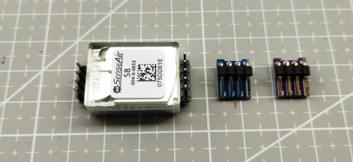
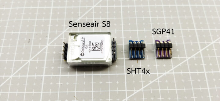
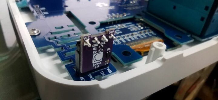
The manufacturer provides the build instructions through this webpage. The assembly instructions are well-written and easy to follow. Basically, I only had three components to install, as shown below.
For the Senseair S8 Module, there are two sets of male headers: one is a 1×4 male header, and the other one is a 1×5 pin male header. I had to place the sensor into the socket on the PCB labeled “CO2 Sensor”, ensuring that the orientation of the sensor was correct.
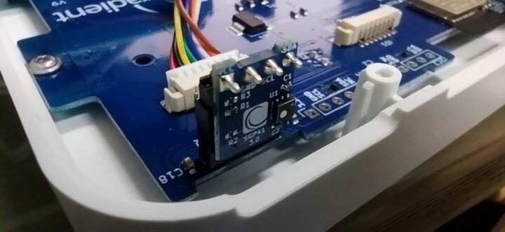
The SGP41 module and the SHT4x module are very similar, with the same number of pins. So, I carefully checked the label on the modules and inserted the SGP41 module into the socket labeled “I2C3” and the SHT1X into the socket labeled “SHT4x”. Note that the silkscreen color of these two modules might differ from what is shown on the instruction webpage: in my case, the SGP41 had a blue silkscreen and the SHT4X had a magenta silkscreen. Also, when installing the modules into the socket, I had to make sure that the modules face outwards, as shown in the following figures.
The PMS sensor uses a JST connector, and in my case, it was already connected to the PCB. So, I just checked to ensure that both ends of the cable are fully plugged.
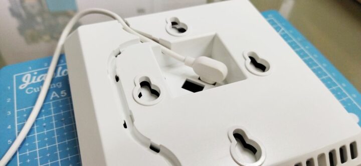
After installing the modules, we can power the device by plugging the USB Type-C into the socket on the back of the enclosure case. There is a cable slot on the backside of the enclosure to hold the cable in place and prevent it from dangling or getting entangled.
After powering the device, it initializes with the default firmware, and the OLED screen lights up, meaning everything works fine. Then, I close the top and bottom covers of the enclosure and securely screw them. Now, it is ready for the next step.
Using the AirGradient ONE air quality monitor
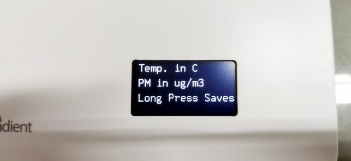
When the device is powered on, there will be a message asking us to configure the unit of measurement. We can enter the configuration screen by long pressing the small button on the backside of the enclosure. By short-pressing the button, we can cycle through the unit for measuring the PM2.5 and the temperature unit as listed below.
- Temperature: °C, PM: ug/m3
- Temperature: °C, PM: US AQI
- Temperature: °F, PM: ug/m3
- Temperature: °F, PM: US AQI
After choosing the preferred units, I long-pressed the button once again to save the configuration and reboot the device.
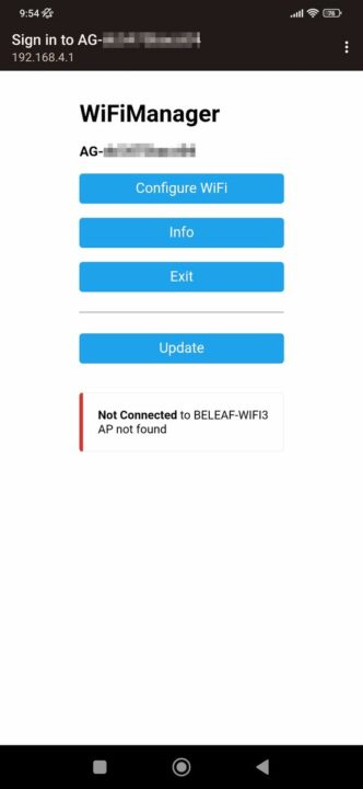
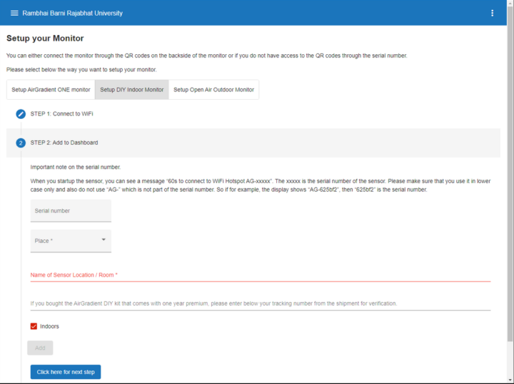
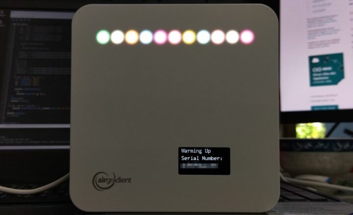
When powering on for the first time, the device will ask to connect to the WiFi. To do this, I had to record the serial number of the device, which will be displayed on the OLED screen during the booting process. I then used my mobile phone to search for the device’s WiFi Hotspot which was named “AG-xxxxxx”, where “xxxxxx” was the serial number of the device.
Once connected to the device’s hotspot, I set the SSID and the password of my target WiFi hotspot and then saved the settings to finish the WiFi configuration.
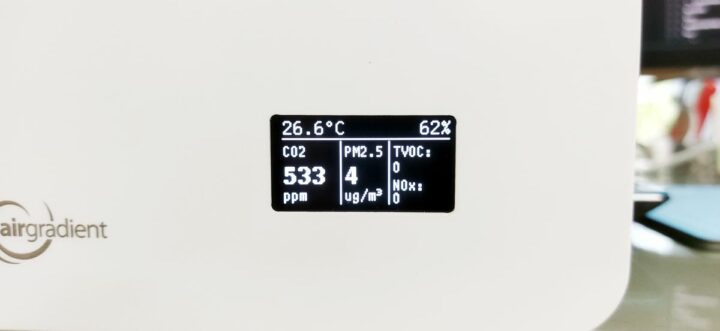
After the configuration screen, the device’s RGB LEDs will show the colors corresponding to the air quality, while the OLED screen will display the data from the sensors using the chosen units. The AirGradient ONE kit will work even if there is no WiFi connection.
Connect to the AirGradient Dashboard
Because there is a USB connection port on the backside of the enclosure, I connected the device to my laptop using the provided USB Type-C cable. I opened the Arduino IDE and observed the messages displayed in the Serial Monitor to check if any messages were being printed. Upon observation, I found that the device was collecting measurement data, including the RSSI of the connected WiFi hotspot, and sending this data to the AirGradient Dashboard server in a JSON format. The default URL is http://hw.airgradient.com/sensors/airgradient:xxxxx/measures, where xxxxx is the serial number of the device. However, the server rejected the request and returned the error message “sensor 'airgradient:xxxxxx' unknown“.
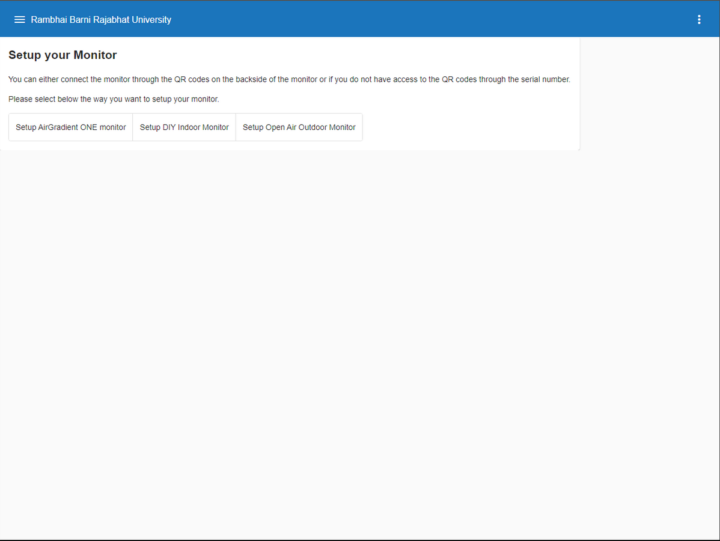
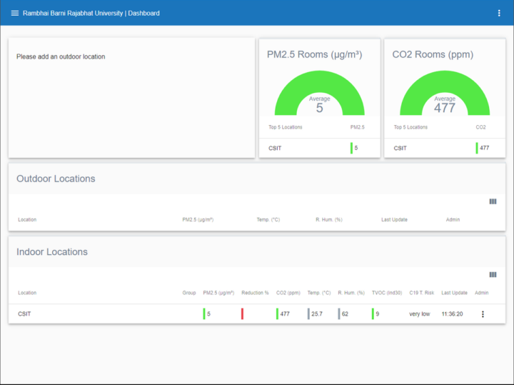
To resolve this issue, I had to create an AirGradient Dashboard account and add information about my device such as the location and the serial number. After successfully creating and adding my device to the dashboard, I restarted the device and waited for a few seconds for the device to connect to the Internet and start sending data. If the connection is successful, we will see something like the following figures.
Flashing the AirGradient Firmware
At the time of this review, there are two methods for flashing the device: direct flashing using the web browser and manual flashing with the Arduino IDE. Here, I decided to use the Arduino IDE to flash my board. For this review, I used the Arduino IDE 1.8.13, which was already installed on my computer. I downloaded the source code from the manufacturer’s GitHub repo and opened the ONE_V9.ino file. As suggested on the web page, I chose the ESP32 platform and selected the Lolin C3 Mini as the target board.
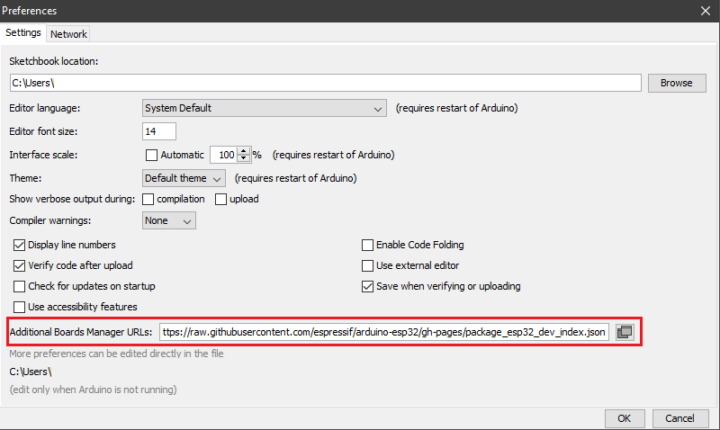
The list of the required libraries is written in the header of the ONE_V9.ino file. In my case, the following six libraries were necessary. You can either use the Library Manager to install these libraries, or download and copy them to Arduino’s libraries manually.
- WifiManager by tzapu, tablatronix tested with version 2.0.11-beta
- U8g2 by oliver tested with version 2.32.15
- Sensirion I2C SGP41 by Sensation Version 0.1.0
- Sensirion Gas Index Algorithm by Sensation Version 3.2.1
- Arduino-SHT by Johannes Winkelmann Version 1.2.2
- Adafruit NeoPixel by Adafruit Version 1.11.0
My first compilation failed because of some missing libraries. In my case, I needed to install these additional libraries.
- PMS Library by Markusz Kakl Version 1.1.0
- S8 UART by Josep Comas Version 1.0.0
- Sensirion Core by Sensirion Version 0.6.0
After installing these libraries, the compilation still failed, but the issues were in the PMS.h and PMS.cpp files. After searching the Internet, I found a solution in this post, which mentioned that the manufacturer used a modified version of the PMS library. So, I needed to update these two files with the following code:
|
1 2 3 4 5 6 7 8 9 10 11 12 13 14 15 16 17 18 19 20 21 22 23 24 25 26 27 28 29 30 31 32 33 34 35 36 37 38 39 40 41 42 43 44 45 46 47 48 49 50 51 52 53 54 55 56 57 58 59 60 61 62 63 64 65 66 67 68 69 70 71 |
#ifndef PMS_H #define PMS_H #include "Stream.h" class PMS { public: static const uint16_t SINGLE_RESPONSE_TIME = 1000; static const uint16_t TOTAL_RESPONSE_TIME = 1000 * 10; static const uint16_t STEADY_RESPONSE_TIME = 1000 * 30; static const uint16_t BAUD_RATE = 9600; struct DATA { // Standard Particles, CF=1 uint16_t PM_SP_UG_1_0; uint16_t PM_SP_UG_2_5; uint16_t PM_SP_UG_10_0; // Atmospheric environment uint16_t PM_AE_UG_1_0; uint16_t PM_AE_UG_2_5; uint16_t PM_AE_UG_10_0; // Raw particles count (number of particles in 0.1l of air uint16_t PM_RAW_0_3; uint16_t PM_RAW_0_5; uint16_t PM_RAW_1_0; uint16_t PM_RAW_2_5; uint16_t PM_RAW_5_0; uint16_t PM_RAW_10_0; // Formaldehyde (HCHO) concentration in mg/m^3 - PMSxxxxST units only uint16_t AMB_HCHO; // Temperature & humidity - PMSxxxxST units only int16_t AMB_TMP; uint16_t AMB_HUM; }; PMS(Stream&); void sleep(); void wakeUp(); void activeMode(); void passiveMode(); void requestRead(); bool read(DATA& data); bool readUntil(DATA& data, uint16_t timeout = SINGLE_RESPONSE_TIME); private: enum STATUS { STATUS_WAITING, STATUS_OK }; enum MODE { MODE_ACTIVE, MODE_PASSIVE }; uint8_t _payload[50]; Stream* _stream; DATA* _data; STATUS _status; MODE _mode = MODE_ACTIVE; uint8_t _index = 0; uint16_t _frameLen; uint16_t _checksum; uint16_t _calculatedChecksum; void loop(); char Char_PM2[10]; }; #endif |
|
1 2 3 4 5 6 7 8 9 10 11 12 13 14 15 16 17 18 19 20 21 22 23 24 25 26 27 28 29 30 31 32 33 34 35 36 37 38 39 40 41 42 43 44 45 46 47 48 49 50 51 52 53 54 55 56 57 58 59 60 61 62 63 64 65 66 67 68 69 70 71 72 73 74 75 76 77 78 79 80 81 82 83 84 85 86 87 88 89 90 91 92 93 94 95 96 97 98 99 100 101 102 103 104 105 106 107 108 109 110 111 112 113 114 115 116 117 118 119 120 121 122 123 124 125 126 127 128 129 130 131 132 133 134 135 136 137 138 139 140 141 142 143 144 145 146 147 148 149 150 151 152 153 154 155 156 157 158 159 160 161 162 163 164 165 166 167 168 169 |
#include "PMS.h" PMS::PMS(Stream& stream) { this->_stream = &stream; } // Standby mode. For low power consumption and prolong the life of the sensor. void PMS::sleep() { uint8_t command[] = { 0x42, 0x4D, 0xE4, 0x00, 0x00, 0x01, 0x73 }; _stream->write(command, sizeof(command)); } // Operating mode. Stable data should be got at least 30 seconds after the sensor wakeup from the sleep mode because of the fan's performance. void PMS::wakeUp() { uint8_t command[] = { 0x42, 0x4D, 0xE4, 0x00, 0x01, 0x01, 0x74 }; _stream->write(command, sizeof(command)); } // Active mode. Default mode after power up. In this mode sensor would send serial data to the host automatically. void PMS::activeMode() { uint8_t command[] = { 0x42, 0x4D, 0xE1, 0x00, 0x01, 0x01, 0x71 }; _stream->write(command, sizeof(command)); _mode = MODE_ACTIVE; } // Passive mode. In this mode sensor would send serial data to the host only for request. void PMS::passiveMode() { uint8_t command[] = { 0x42, 0x4D, 0xE1, 0x00, 0x00, 0x01, 0x70 }; _stream->write(command, sizeof(command)); _mode = MODE_PASSIVE; } // Request read in Passive Mode. void PMS::requestRead() { if (_mode == MODE_PASSIVE) { uint8_t command[] = { 0x42, 0x4D, 0xE2, 0x00, 0x00, 0x01, 0x71 }; _stream->write(command, sizeof(command)); } } // Non-blocking function for parse response. bool PMS::read(DATA& data) { _data = &data; loop(); return _status == STATUS_OK; } // Blocking function for parse response. Default timeout is 1s. bool PMS::readUntil(DATA& data, uint16_t timeout) { _data = &data; uint32_t start = millis(); do { loop(); if (_status == STATUS_OK) break; } while (millis() - start < timeout); return _status == STATUS_OK; } void PMS::loop() { _status = STATUS_WAITING; if (_stream->available()) { uint8_t ch = _stream->read(); switch (_index) { case 0: if (ch != 0x42) { return; } _calculatedChecksum = ch; break; case 1: if (ch != 0x4D) { _index = 0; return; } _calculatedChecksum += ch; break; case 2: _calculatedChecksum += ch; _frameLen = ch << 8; break; case 3: _frameLen |= ch; // Unsupported sensor, different frame length, transmission error e.t.c. if (_frameLen != 2 * 9 + 2 && _frameLen != 2 * 13 + 2) { _index = 0; return; } _calculatedChecksum += ch; break; default: if (_index == _frameLen + 2) { _checksum = ch << 8; } else if (_index == _frameLen + 2 + 1) { _checksum |= ch; if (_calculatedChecksum == _checksum) { _status = STATUS_OK; // Standard Particles, CF=1. _data->PM_SP_UG_1_0 = makeWord(_payload[0], _payload[1]); _data->PM_SP_UG_2_5 = makeWord(_payload[2], _payload[3]); _data->PM_SP_UG_10_0 = makeWord(_payload[4], _payload[5]); // Atmospheric Environment. _data->PM_AE_UG_1_0 = makeWord(_payload[6], _payload[7]); _data->PM_AE_UG_2_5 = makeWord(_payload[8], _payload[9]); _data->PM_AE_UG_10_0 = makeWord(_payload[10], _payload[11]); // Total particles count per 100ml air _data->PM_RAW_0_3 = makeWord(_payload[12], _payload[13]); _data->PM_RAW_0_5 = makeWord(_payload[14], _payload[15]); _data->PM_RAW_1_0 = makeWord(_payload[16], _payload[17]); _data->PM_RAW_2_5 = makeWord(_payload[18], _payload[19]); _data->PM_RAW_5_0 = makeWord(_payload[20], _payload[21]); _data->PM_RAW_10_0 = makeWord(_payload[22], _payload[23]); // Formaldehyde concentration (PMSxxxxST units only) _data->AMB_HCHO = makeWord(_payload[24], _payload[25]) / 1000; // Temperature & humidity (PMSxxxxST units only) _data->AMB_TMP = makeWord(_payload[20], _payload[21]); _data->AMB_HUM = makeWord(_payload[22], _payload[23]); } _index = 0; return; } else { _calculatedChecksum += ch; uint8_t payloadIndex = _index - 4; // Payload is common to all sensors (first 2x6 bytes). if (payloadIndex < sizeof(_payload)) { _payload[payloadIndex] = ch; } } break; } _index++; } } |
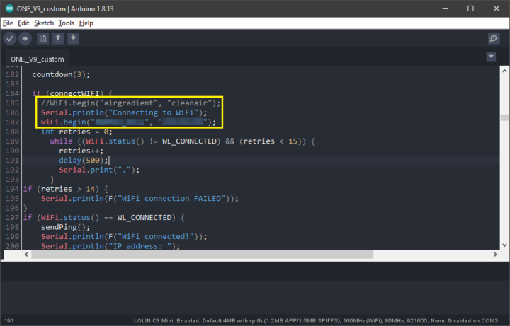
The compiling and uploading were done successfully. However, I figured out that the device couldn’t connect to the WiFi. So, I decided to solve this problem by hardcoding the SSID and password manually. After this, the device worked as normal.
Open-sourceness
Customizing Arduino source code
As mentioned above, we can access the source code on GitHub, and not only the firmware for this kit, but also the firmware for other versions, and some examples are available there.
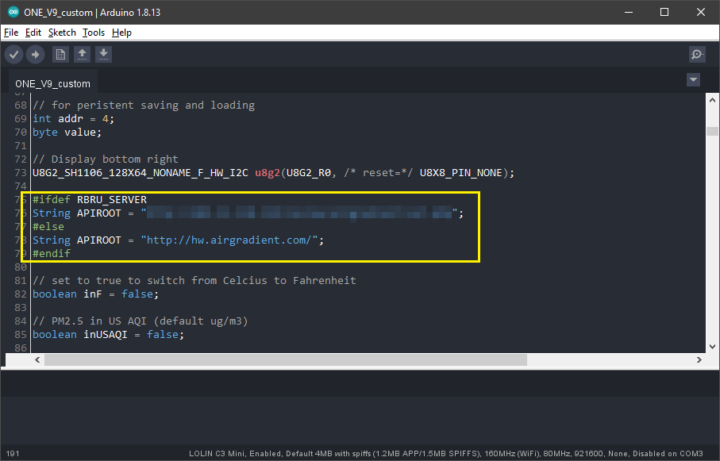
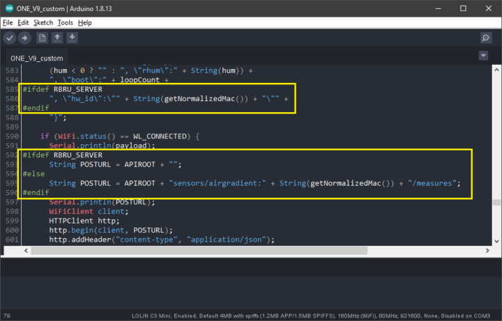
I then modified the source code (ONE_V9.ino) to send the data to my own server by changing the value of the APIROOT variable at the top of the source code to the URL of my own server. Then, I modified the sendToServer() function by appending the device’s serial number to the HTTP request. After updating the value of the POSTURL string to match my requirement, I compiled and uploaded the new firmware to the device. After a few seconds, the device started sending the data to my own server successfully.
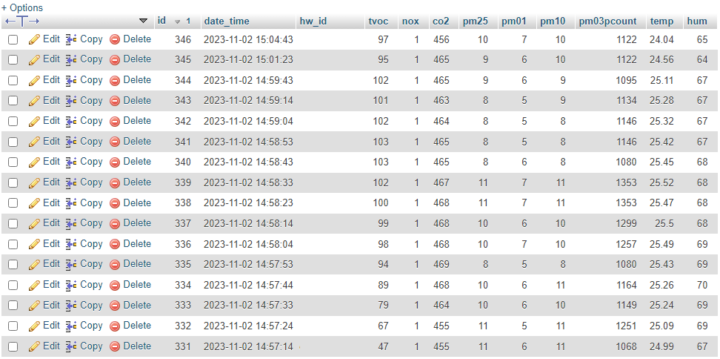
Since the 11 RGB LEDs are programmable, I continued modifying the source code to change the behavior of the LEDs. With the default configuration, these LEDs are turned off during booting and will be turned on after the device goes into the main screen.
Since the device uses Adafruit’s NeoPixel library, I can control the color of each LED by simply calling the setPixelColor function with the desired LED index and the values of RGB components. Therefore, I added the following code at the end of the setup function to make the LEDs light randomly for a few seconds before returning to the normal state.
|
1 2 3 4 5 6 7 8 9 10 11 12 13 14 15 16 17 18 19 20 21 22 23 24 25 26 27 28 29 30 31 |
void setup() { ... int i; int j; int r; int g; int b; for(i = 0; i < 11; i++) { pixels.setPixelColor(i, pixels.Color(0, 0, 0)); delay(1); } pixels.show(); for(i = 0; i < 32; i++) { for(j = 0; j < 11; j++) { r = random(0, 256); g = random(0, 256); b = random(0, 256); pixels.setPixelColor( j, pixels.Color(r, g, b)); } delay(50); pixels.show(); } for(i = 0; i < 11; i++) { pixels.setPixelColor(i, pixels.Color(0, 0, 0)); } pixels.show(); } |
Hardware design files
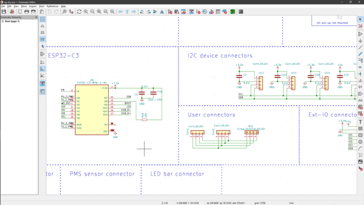
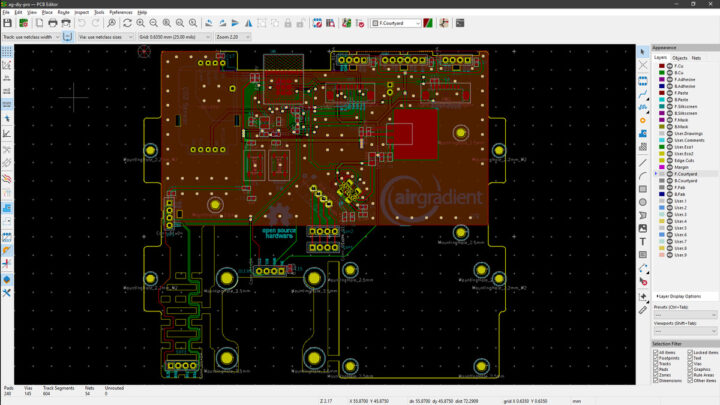
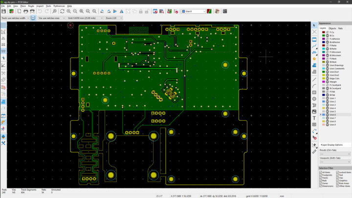
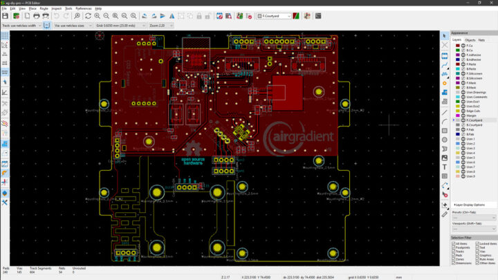
Not only are the source codes available, but the schematic diagrams and the PCB files are also accessible for developers through this webpage. These files are in KiCad format, and I was able to open them using KiCad 7.0 without any problems.
3D print your own enclosure
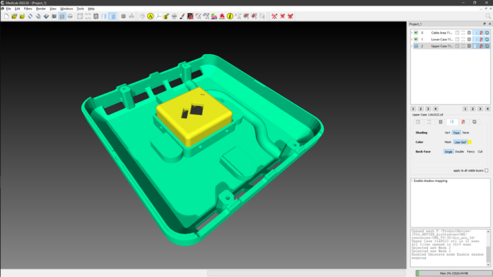
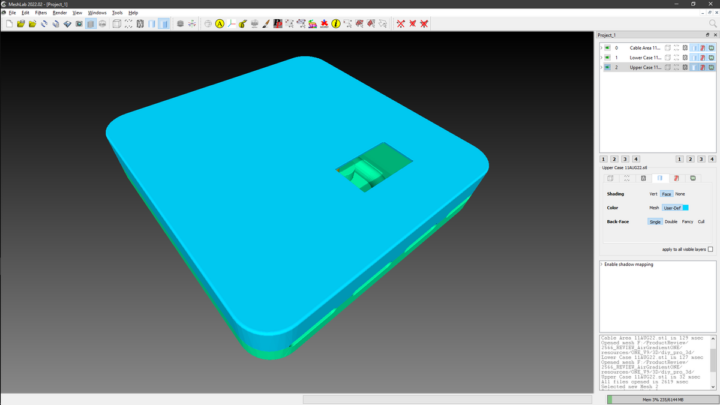
The manufacturer also provides developers with 3D models of the enclosure. These models are in STL format and can be downloaded through this webpage where two ZIP files are available for download: one for the enclosure and the other for the clip-on stand.
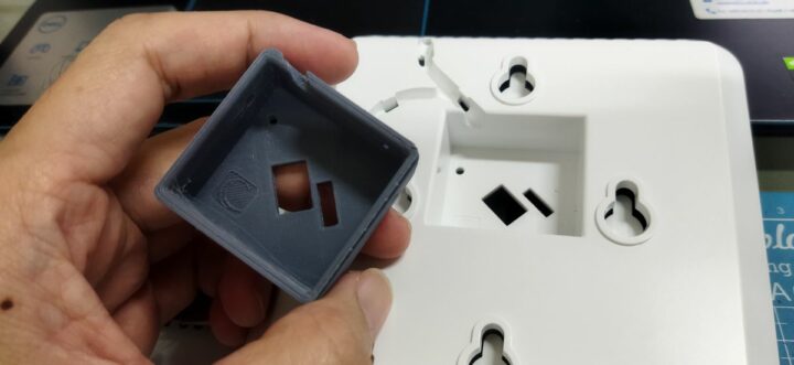
The 3D enclosure model is composed of three models: the lower case, the upper case, and the cable area models. I visualized these 3D models by opening the STL files in the MeshLab software, as shown in the following figures. I also tested printing the cable area model by slicing the STL file with PrusaSlicer 2.6.0 and printing it using Printrun 2.1. This model was easy to print, and the printed model is shown in the following figure.
Conclusion
AirGradient ONE indoor air quality monitor works very well, although when observing the messages over the serial port, I noticed that measurement values are sometimes unstable after restarting the device. Fortunately, they stabilize within a few seconds. The open-sourceness of the device also enables customization of the firmware, electronics, and enclosure.
I would like to thank AirGradient for providing the One Kit air quality monitor for this review. You can order the fully assembled and tested version of this AirGradient ONE for $195, or the kit version reviewed here for $138, on the manufacturer’s website.

My main research areas are digital image/audio processing, digital photogrammetry, AI, IoT, and UAV. I am open to other subjects as well.
Support CNX Software! Donate via cryptocurrencies, become a Patron on Patreon, or purchase goods on Amazon or Aliexpress





Great review, Mr. Teeravech!
This seems like a really useful product that a lot of people would be interested in. Thanks for sharing!
The various oxides of nitrogen are indeed bad, but no detection of the other really dangerous gases carbon monoxide, methane, or radon …
Carbon monoxide is often built into smoke alarms and treated similarly: if it’s detected (over some small threshold), sound the alarm so the house can be immediately evacuated. The things the AirGradient detects are more stuff you track/graph and try to minimize but don’t immediately flee from. The device has a LCD display and network connectivity but no audible alarm.
There are threads like this one about radon on their forums, but IIUC no one could find an inexpensive sensor.
Just received my kit in the mail yesterday and set it up. Like you, I had issues with the dashboard (error 422 upon setting up an account), but was able to verify readings from the display and flash the firmware via USB. I didn’t have much time to fiddle, but I plan to try and put together a working ESPHome config this weekend.
Very thorough review. Great job.
I’ve been using this for several months with Home Assistant.
Simple to Assemble.
Works well
No Problems
If it had Radon detection it would be perfect