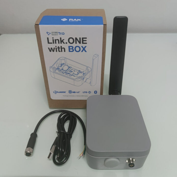
RAKwireless has sent us a review sample of the WisTrio Link.ONE all-in-one LPWAN IoT development kit with support for LTE-M, NB-IoT, and LoRaWAN connectivity and programmable with the Arduino IDE. We’ve tested the kit with its weatherproof WisBlock Unify enclosure using LoRaWAN connectivity and open-source software packages and frameworks such as ChipStark, Node-Red, InfluxDB, and Grafana.
Key features of the Link.ONE kit
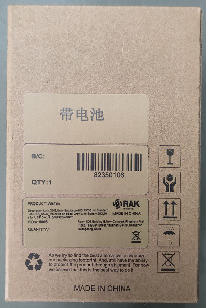
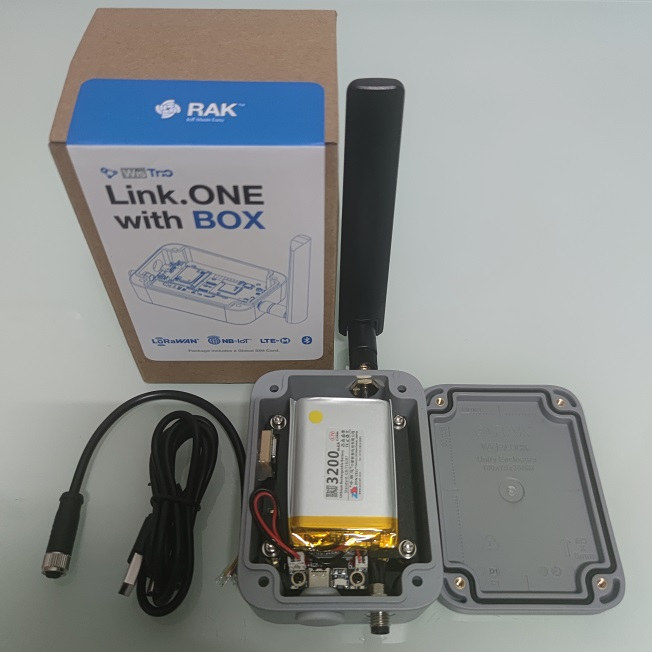
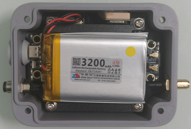
The Link.ONE kit we’ve received comes with a WisBlock Unify Enclosure (100 x 75 x 38 mm) and a 3,200 mAh/3.7V rechargeable lithium battery which is sufficient when the system is mostly in sleep mode and used to receive data, while not sending information too often.
“Link.ONE with BOX” unboxing
The following items were very tightly packed inside the box:
- WisTrio LTE-M, NB-IoT, and LoRaWAN development board
- Rechargeable lithium battery
- External Antenna for cellular
- USB Type-C cable
- Circular M8 female cable
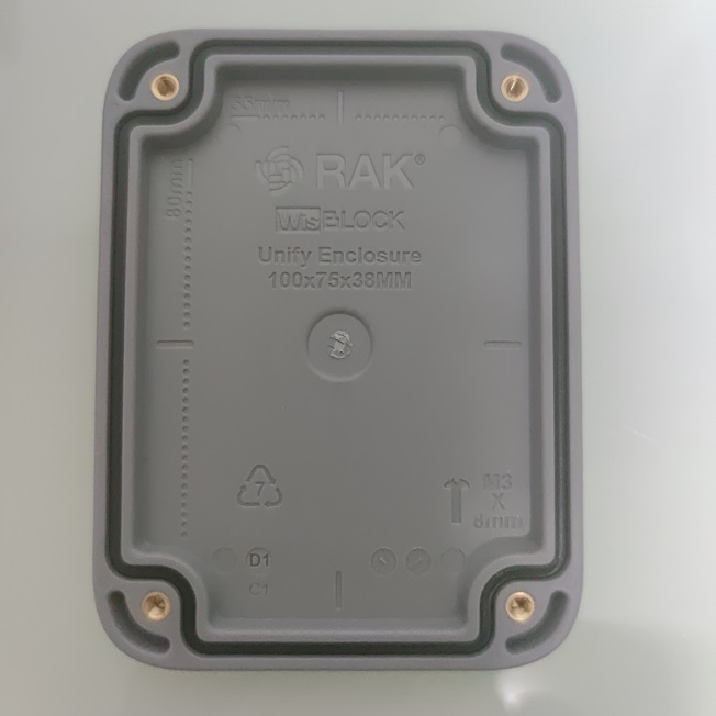
The enclosure is strong with the lid having a waterproof rubber to ensure IP65 ingress protection rating – and weatherproofness – when the enclosure is closed.
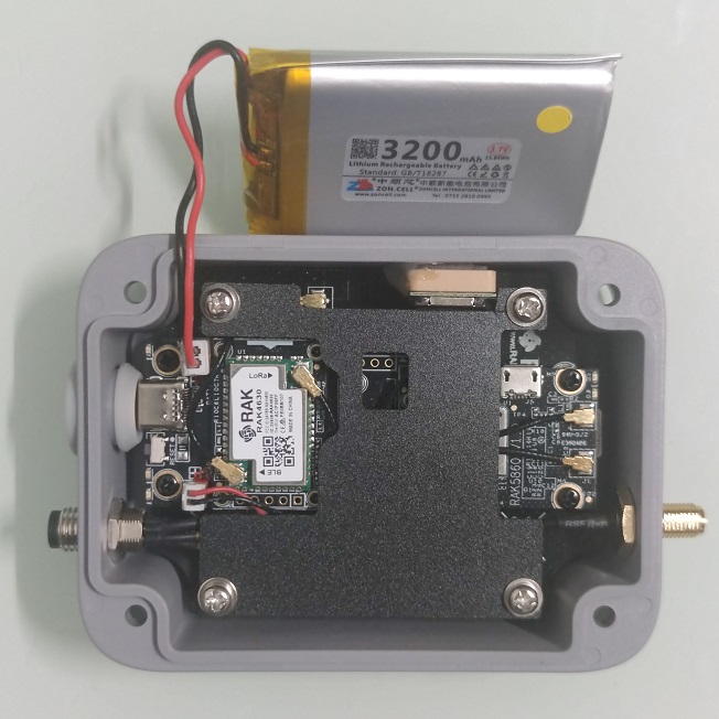
If we remove the battery, we can have a closer look at the WisTrio Link.ONE development board.
Modules used in the Link.ONE development kit
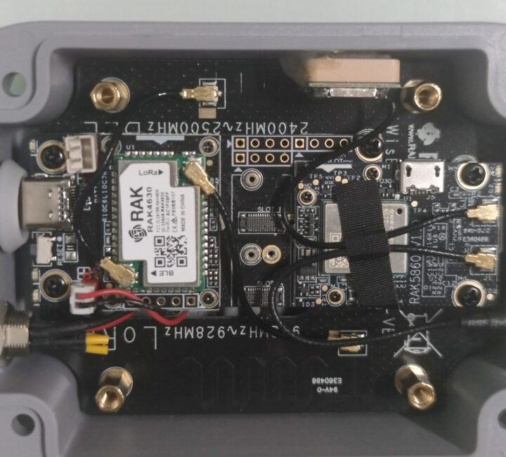
There are three main modules in the kit:
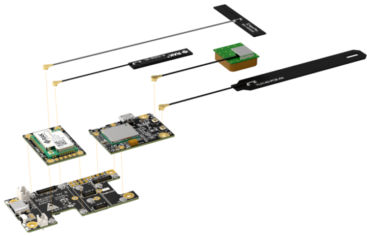
- RAK4631 WisBlock core module with a Nordic Semi nRF52840 BLE microcontroller and a Semtech SX1262 (LoRA/LoRaWAN) RF transceiver
- RAK5860 WisBlock NB-IoT interface module based on Quectel BG77 with NB-IoT, LTE-M, and GPS
- RAK19007 WisBlock baseboard with a USB Type-C port and a Li-ion charger
Everything is assembled as shown in the illustration below.
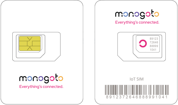
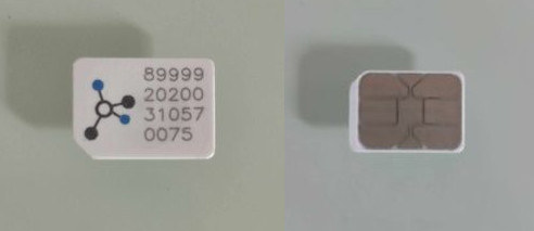
The kit also includes a Monogoto SIM card with 500 MB of cellular data that can be used for up to 10 years.
The SIM card can be used globally, but we are based in Thailand, and the SIM card works with 2G, 3G, and 4G cellular networks using AIS or TrueMove operators, but not LTE Cat M1 (LTE-M), and there’s no information about NB-IoT. More about that later.
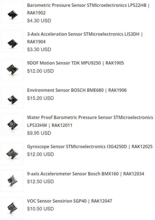
In addition, various sensor modules can be added to the Link.ONE devkit at the time of order, but none were included in our kit.
LPWAN (Low Power Wide Area Network)
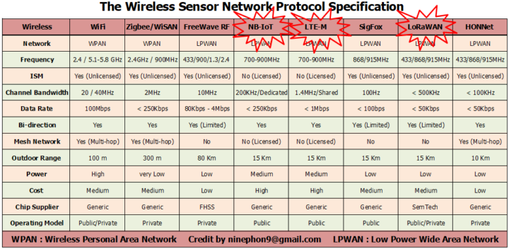
Link.ONE supports three types of low-power wide area networks (LPWAN): LTE-M, NB-IoT, and LoRaWAN.
- NB-IoT (Narrow Band Internet of Things) is a technology that has been developed from 4G LTE to allow IoT devices to connect wirelessly through a cellular network. It is suitable for applications that do not require high data transmission speed, such as Smart Parking or Smart Metering.
- LTE-M (Long Term Evolution of Machines) is a technology similar to NB-IoT but with a higher data transmission speed, while still saving energy compared to a traditional 4G LTE data connection. It is suitable for device location-tracking applications such as Smart Transportation and Asset Tracking.
- LoRaWAN (Long Range Wide Area Network) is a radio technology based on the LoRa protocol designed to support low-power device connectivity and communicate data over a long distance across the network. It supports both Private and Public networks, the former meaning you can install your own gateway instead of relying on an operator.
Note 1 – The reviewer did not test the NB-IoT connection due to the annual fee for Network Server on Cloud from operators in Thailand.
Note 2. The reviewer did not test the LTE-M connection because it is not supported by the Monogoto SIM card in Thailand.
Private LoRaWAN IoT on-premise platform
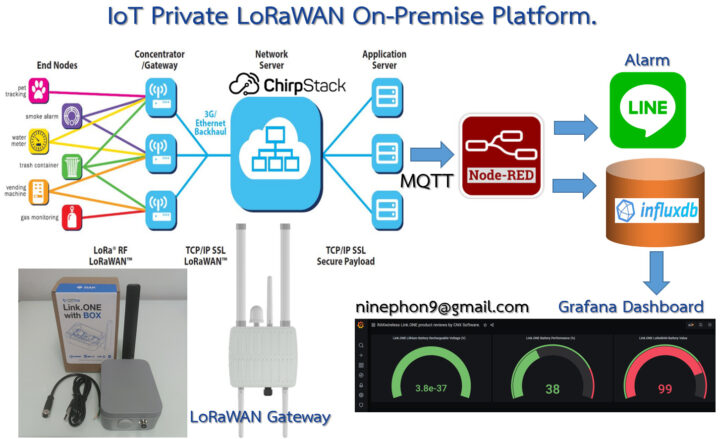
The reviewer has set up a private LoRaWAN IoT platform bringing the convenience of managing the LoRaWAN system completely. The platform comes with various open-source software as follows.
- ChirpStack open-source LoRaWAN network and application server that registers the LoRaWAN IoT device number and decrypts the received data in AES128 format through an MQTT broker (Message Queuing Telemetry Transport) acting as the sender (publish).
- Node-RED flow-based development tool for programming. It is a recipient (subscribe) from ChirpStack via the MQTT protocol and takes the data from the payload and decodes it according to the BASE64 format. It will store the sensor data in an InfluxDB database, and check and configure notification settings in the LINE Notify Application.
- InfluxDB is an open-source time series database that stores sensor and LoRaWAN gateway data, and automatically sorts it by time series allowing us to analyze the data for any period of time.
- Grafana real-time dashboard to visualize the data from the InfluxDB database in different ways.
- LINE Notify – When the sensor is higher or lower than a specified value, the LINE messaging application will notify us via the LINE Notify API only once, meaning there will be no notification for duplicate values.
Hardware and software preparations
The hardware required includes the Link.ONE development kit, a USB Type-C cable, a LoRaWAN gateway, and a computer.
We’ll also need to install the Arduino IDE and set it up for the Link.ONE devkit as follows:
- Install the Arduino IDE
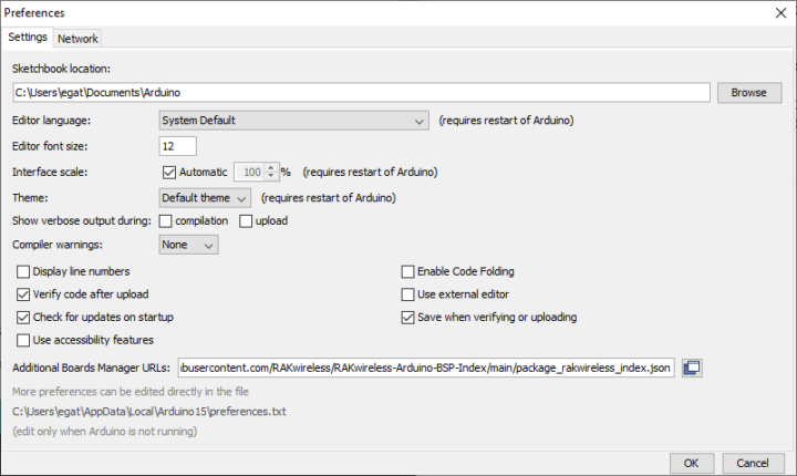
- Added the Link.ONE device. Go to the Arduino IDE menu File -> Preferences and paste the URL https://raw.githubusercontent.com/RAKwireless/RAKwireless-Arduino-BSP-Index/main/package_rakwireless_index.json to the field Additional Boards Manager URLs.
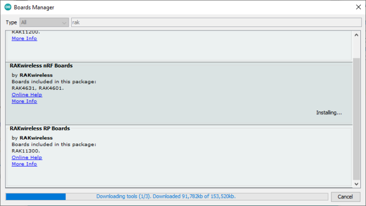
- Then click on Tools -> Board -> Board Manager, search for “RAKwireless nRF Boards”, and install the package for WisBlock RAK4631
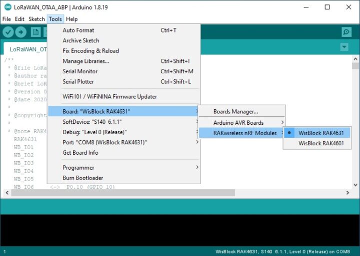
- Go to Tools -> Board -> Board Manager -> RAKwireless nRF Boards -> WisBlock RAK4631 to select the Link.ONE board.
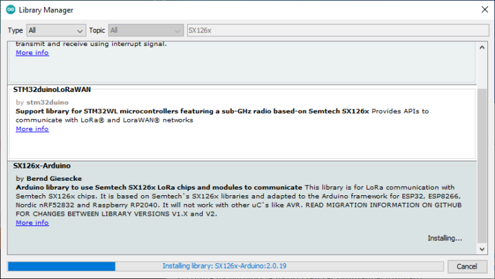
- Add the SX126x library by going to the Arduino menu and selecting Sketch -> Include Library -> Library Manager before searching for “SX126x-Arduino” and installing the library.
LoRaWAN tests on Line.ONE devkit
We’ll write a “Hello World” program to send a message to Link.ONE over LoRaWAN. We’ve set the operating frequency band to AS923 for Thailand, and set up the connection as OTAA using the following values:
- DevEUI = 88 88 88 88 88 88 33 33
- AppKey = 88 88 88 88 88 88 88 88 88 88 88 88 88 88 88 88
- AppEUI = B8 27 E B FF FE 39 00 00
Note: There are 2 types of Activation processes: ABP (Activation By Personalization) and OTAA (Over The Air Activation).
|
1 2 3 4 5 6 7 8 9 10 11 12 13 14 15 16 17 18 19 20 21 22 23 24 25 26 27 28 29 30 31 32 33 34 35 36 37 38 39 40 41 42 43 44 45 46 47 48 49 50 51 52 53 54 55 56 57 58 59 60 61 62 63 64 65 66 67 68 69 70 71 72 73 74 75 76 77 78 79 80 81 82 83 84 85 86 87 88 89 90 91 92 93 94 95 96 97 98 99 100 101 102 103 104 105 106 107 108 109 110 111 112 113 114 115 116 117 118 119 120 121 122 123 124 125 126 127 128 129 130 131 132 133 134 135 136 137 138 139 140 141 142 143 144 145 146 147 148 149 150 151 152 153 154 155 156 157 158 159 160 161 162 163 164 165 166 167 168 169 170 171 172 173 174 175 176 177 178 179 180 181 182 183 184 185 186 187 188 189 190 191 192 193 194 195 196 197 198 199 200 201 202 203 204 205 206 207 208 209 210 211 212 213 214 215 216 217 218 219 220 221 222 223 224 225 226 227 228 229 230 231 232 233 234 235 236 237 238 239 240 241 242 243 244 245 246 247 248 249 250 251 252 253 254 255 256 257 258 259 260 261 262 263 264 265 266 267 268 269 270 271 272 273 274 275 276 277 278 279 280 281 282 283 284 285 286 287 288 289 290 291 292 293 294 295 296 297 298 299 300 301 302 |
/** * @file LoRaWAN_OTAA_ABP.ino * @author rakwireless.com * @brief LoRaWan node example with OTAA/ABP registration * @version 0.1 * @date 2020-08-21 * * @copyright Copyright (c) 2020 * * @note RAK4631 GPIO mapping to nRF52840 GPIO ports RAK4631 <-> nRF52840 WB_IO1 <-> P0.17 (GPIO 17) WB_IO2 <-> P1.02 (GPIO 34) WB_IO3 <-> P0.21 (GPIO 21) WB_IO4 <-> P0.04 (GPIO 4) WB_IO5 <-> P0.09 (GPIO 9) WB_IO6 <-> P0.10 (GPIO 10) WB_SW1 <-> P0.01 (GPIO 1) WB_A0 <-> P0.04/AIN2 (AnalogIn A2) WB_A1 <-> P0.31/AIN7 (AnalogIn A7) */ #include <Arduino.h> #include <LoRaWan-RAK4630.h> //http://librarymanager/All#SX126x #include <SPI.h> // RAK4630 supply two LED #ifndef LED_BUILTIN #define LED_BUILTIN 35 #endif #ifndef LED_BUILTIN2 #define LED_BUILTIN2 36 #endif bool doOTAA = true; // OTAA is used by default. #define SCHED_MAX_EVENT_DATA_SIZE APP_TIMER_SCHED_EVENT_DATA_SIZE /**< Maximum size of scheduler events. */ #define SCHED_QUEUE_SIZE 60 /**< Maximum number of events in the scheduler queue. */ #define LORAWAN_DATERATE DR_0 /*LoRaMac datarates definition, from DR_0 to DR_5*/ #define LORAWAN_TX_POWER TX_POWER_5 /*LoRaMac tx power definition, from TX_POWER_0 to TX_POWER_15*/ #define JOINREQ_NBTRIALS 3 /**< Number of trials for the join request. */ DeviceClass_t g_CurrentClass = CLASS_A; /* class definition*/ LoRaMacRegion_t g_CurrentRegion = LORAMAC_REGION_AS923; /* Region: AS923 */ lmh_confirm g_CurrentConfirm = LMH_UNCONFIRMED_MSG; /* confirm/unconfirm packet definition*/ uint8_t gAppPort = LORAWAN_APP_PORT; /* data port*/ /**@brief Structure containing LoRaWan parameters, needed for lmh_init() */ static lmh_param_t g_lora_param_init = {LORAWAN_ADR_ON, LORAWAN_DATERATE, LORAWAN_PUBLIC_NETWORK, JOINREQ_NBTRIALS, LORAWAN_TX_POWER, LORAWAN_DUTYCYCLE_OFF}; // Foward declaration static void lorawan_has_joined_handler(void); static void lorawan_join_failed_handler(void); static void lorawan_rx_handler(lmh_app_data_t *app_data); static void lorawan_confirm_class_handler(DeviceClass_t Class); static void send_lora_frame(void); /**@brief Structure containing LoRaWan callback functions, needed for lmh_init() */ static lmh_callback_t g_lora_callbacks = {BoardGetBatteryLevel, BoardGetUniqueId, BoardGetRandomSeed, lorawan_rx_handler, lorawan_has_joined_handler, lorawan_confirm_class_handler, lorawan_join_failed_handler }; //OTAA keys !!!! KEYS ARE MSB !!!! uint8_t nodeDeviceEUI[8] = {0x88, 0x88, 0x88, 0x88, 0x88, 0x88, 0x33, 0x33}; uint8_t nodeAppEUI[8] = {0xB8, 0x27, 0xEB, 0xFF, 0xFE, 0x39, 0x00, 0x00}; uint8_t nodeAppKey[16] = {0x88, 0x88, 0x88, 0x88, 0x88, 0x88, 0x88, 0x88, 0x88, 0x88, 0x88, 0x88, 0x88, 0x88, 0x88, 0x88}; // ABP keys uint32_t nodeDevAddr = 0x260116F8; uint8_t nodeNwsKey[16] = {0x7E, 0xAC, 0xE2, 0x55, 0xB8, 0xA5, 0xE2, 0x69, 0x91, 0x51, 0x96, 0x06, 0x47, 0x56, 0x9D, 0x23}; uint8_t nodeAppsKey[16] = {0xFB, 0xAC, 0xB6, 0x47, 0xF3, 0x58, 0x45, 0xC7, 0x50, 0x7D, 0xBF, 0x16, 0x8B, 0xA8, 0xC1, 0x7C}; // Private defination #define LORAWAN_APP_DATA_BUFF_SIZE 64 /**< buffer size of the data to be transmitted. */ #define LORAWAN_APP_INTERVAL 20000 /**< Defines for user timer, the application data transmission interval. 20s, value in [ms]. */ static uint8_t m_lora_app_data_buffer[LORAWAN_APP_DATA_BUFF_SIZE]; //< Lora user application data buffer. static lmh_app_data_t m_lora_app_data = {m_lora_app_data_buffer, 0, 0, 0, 0}; //< Lora user application data structure. TimerEvent_t appTimer; static uint32_t timers_init(void); static uint32_t count = 0; static uint32_t count_fail = 0; void setup() { pinMode(LED_BUILTIN, OUTPUT); digitalWrite(LED_BUILTIN, LOW); // Initialize Serial for debug output time_t timeout = millis(); Serial.begin(115200); while (!Serial) { if ((millis() - timeout) < 5000) { delay(100); } else { break; } } // Initialize LoRa chip. lora_rak4630_init(); Serial.println("====================================="); Serial.println("Welcome to RAK4630 LoRaWan!!!"); if (doOTAA) { Serial.println("Type: OTAA"); } else { Serial.println("Type: ABP"); } switch (g_CurrentRegion) { case LORAMAC_REGION_AS923: Serial.println("Region: AS923"); break; case LORAMAC_REGION_AU915: Serial.println("Region: AU915"); break; case LORAMAC_REGION_CN470: Serial.println("Region: CN470"); break; case LORAMAC_REGION_CN779: Serial.println("Region: CN779"); break; case LORAMAC_REGION_EU433: Serial.println("Region: EU433"); break; case LORAMAC_REGION_IN865: Serial.println("Region: IN865"); break; case LORAMAC_REGION_EU868: Serial.println("Region: EU868"); break; case LORAMAC_REGION_KR920: Serial.println("Region: KR920"); break; case LORAMAC_REGION_US915: Serial.println("Region: US915"); break; case LORAMAC_REGION_RU864: Serial.println("Region: RU864"); break; case LORAMAC_REGION_AS923_2: Serial.println("Region: AS923-2"); break; case LORAMAC_REGION_AS923_3: Serial.println("Region: AS923-3"); break; case LORAMAC_REGION_AS923_4: Serial.println("Region: AS923-4"); break; } Serial.println("====================================="); //creat a user timer to send data to server period uint32_t err_code; err_code = timers_init(); if (err_code != 0) { Serial.printf("timers_init failed - %d\n", err_code); return; } // Setup the EUIs and Keys if (doOTAA) { lmh_setDevEui(nodeDeviceEUI); lmh_setAppEui(nodeAppEUI); lmh_setAppKey(nodeAppKey); } else { lmh_setNwkSKey(nodeNwsKey); lmh_setAppSKey(nodeAppsKey); lmh_setDevAddr(nodeDevAddr); } // Initialize LoRaWan err_code = lmh_init(&g_lora_callbacks, g_lora_param_init, doOTAA, g_CurrentClass, g_CurrentRegion); if (err_code != 0) { Serial.printf("lmh_init failed - %d\n", err_code); return; } // Start Join procedure lmh_join(); } void loop() { // Put your application tasks here, like reading of sensors, // Controlling actuators and/or other functions. } /**@brief LoRa function for handling HasJoined event. */ void lorawan_has_joined_handler(void) { if(doOTAA == true) { Serial.println("OTAA Mode, Network Joined!"); } else { Serial.println("ABP Mode"); } lmh_error_status ret = lmh_class_request(g_CurrentClass); if (ret == LMH_SUCCESS) { delay(1000); TimerSetValue(&appTimer, LORAWAN_APP_INTERVAL); TimerStart(&appTimer); } } /**@brief LoRa function for handling OTAA join failed */ static void lorawan_join_failed_handler(void) { Serial.println("OTAA join failed!"); Serial.println("Check your EUI's and Keys's!"); Serial.println("Check if a Gateway is in range!"); } /**@brief Function for handling LoRaWan received data from Gateway * * @param[in] app_data Pointer to rx data */ void lorawan_rx_handler(lmh_app_data_t *app_data) { Serial.printf("LoRa Packet received on port %d, size:%d, rssi:%d, snr:%d, data:%s\n", app_data->port, app_data->buffsize, app_data->rssi, app_data->snr, app_data->buffer); } void lorawan_confirm_class_handler(DeviceClass_t Class) { Serial.printf("switch to class %c done\n", "ABC"[Class]); // Informs the server that switch has occurred ASAP m_lora_app_data.buffsize = 0; m_lora_app_data.port = gAppPort; lmh_send(&m_lora_app_data, g_CurrentConfirm); } void send_lora_frame(void) { if (lmh_join_status_get() != LMH_SET) { //Not joined, try again later return; } uint32_t i = 0; memset(m_lora_app_data.buffer, 0, LORAWAN_APP_DATA_BUFF_SIZE); m_lora_app_data.port = gAppPort; m_lora_app_data.buffer[i++] = 'N'; m_lora_app_data.buffer[i++] = 'i'; m_lora_app_data.buffer[i++] = 'n'; m_lora_app_data.buffer[i++] = 'e'; m_lora_app_data.buffer[i++] = 'P'; m_lora_app_data.buffer[i++] = 'h'; m_lora_app_data.buffer[i++] = 'o'; m_lora_app_data.buffer[i++] = 'n'; m_lora_app_data.buffsize = i; lmh_error_status error = lmh_send(&m_lora_app_data, g_CurrentConfirm); if (error == LMH_SUCCESS) { count++; Serial.printf("lmh_send ok count %d\n", count); } else { count_fail++; Serial.printf("lmh_send fail count %d\n", count_fail); } } /**@brief Function for handling user timerout event. */ void tx_lora_periodic_handler(void) { TimerSetValue(&appTimer, LORAWAN_APP_INTERVAL); TimerStart(&appTimer); Serial.println("Sending frame now..."); send_lora_frame(); } /**@brief Function for the Timer initialization. * * @details Initializes the timer module. This creates and starts application timers. */ uint32_t timers_init(void) { TimerInit(&appTimer, tx_lora_periodic_handler); return 0; } |
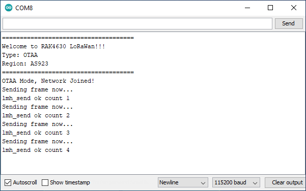
We can now compile the code in the Arduino IDE and upload/flash it to the Link.ONE board. Note that we can flash/program the board immediately without pressing any button and the board will work as programmed automatically. This is an advantage of Link.ONE for developers.
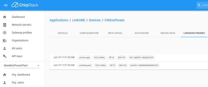
When the program runs two types of messages are processed:
- A “Join Request” where the Link.ONE makes a request to connect to the LoRaWAN Network Server through the LoRaWAN Gateway.
- A “Join Accept” where the LoRaWAN Network Server will check Link.ONE DeviceEUI number, and if it is already registered, it will accept requests to send and receive data to each other.
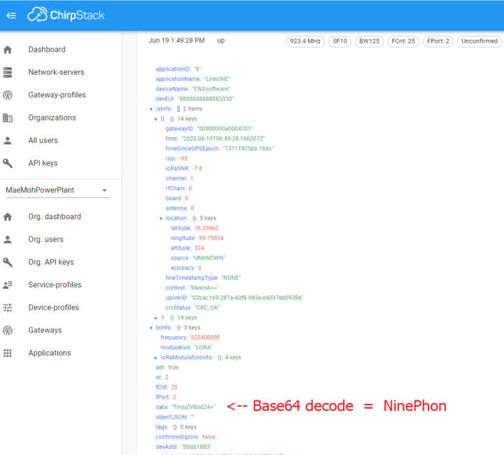
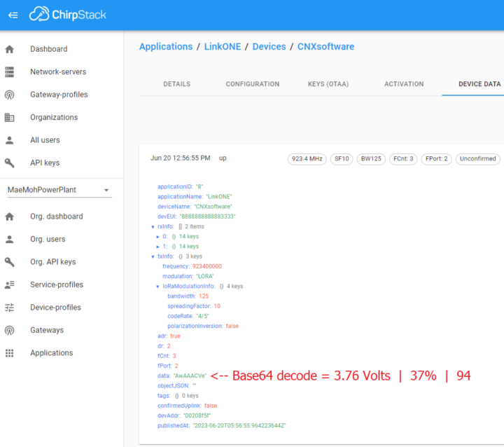
The payload data is “TmluZVBob24=” as can be seen from the screenshot below. It decodes to “NinePhon” (the reviewer’s name) when using the Base64 decode standard.
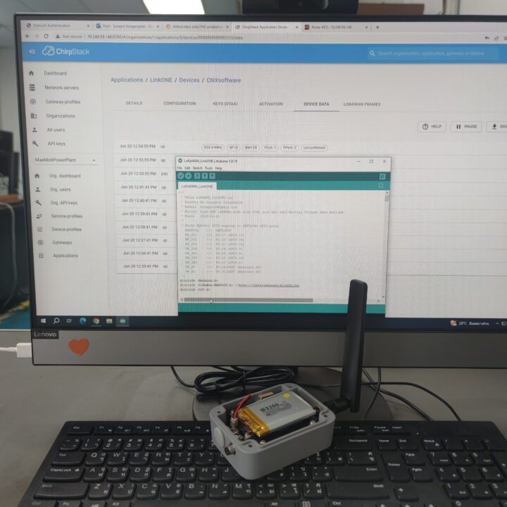
Since RAKwireless did not include a sensor module in the kit, we wrote a second demo program to read the battery voltage, the battery level in percent, and a “battery value” from the Lithium-ion batteries.
|
1 2 3 4 5 6 7 8 9 10 11 12 13 14 15 16 17 18 19 20 21 22 23 24 25 26 27 28 29 30 31 32 33 34 35 36 37 38 39 40 41 42 43 44 45 46 47 48 49 50 51 52 53 54 55 56 57 58 59 60 61 62 63 64 65 66 67 68 69 70 71 72 73 74 75 76 77 78 79 80 81 82 83 84 85 86 87 88 89 90 91 92 93 94 95 96 97 98 99 100 101 102 103 104 105 106 107 108 109 110 111 112 113 114 115 116 117 118 119 120 121 122 123 124 125 126 127 128 129 130 131 132 133 134 135 136 137 138 139 140 141 142 143 144 145 146 147 148 149 150 151 152 153 154 155 156 157 158 159 160 161 162 163 164 165 166 167 168 169 170 171 172 173 174 175 176 177 178 179 180 181 182 183 184 185 186 187 188 189 190 191 192 193 194 195 196 197 198 199 200 201 202 203 204 205 206 207 208 209 210 211 212 213 214 215 216 217 218 219 220 221 222 223 224 225 226 227 228 229 230 231 232 233 234 235 236 237 238 239 240 241 242 243 244 245 246 247 248 249 250 251 252 253 254 255 256 257 258 259 260 261 262 263 264 265 266 267 268 269 270 271 272 273 274 275 276 277 278 279 280 281 282 283 284 285 286 287 288 289 290 291 292 293 294 295 296 297 298 299 300 301 302 303 304 305 306 307 308 309 310 311 312 313 314 315 316 317 318 319 320 321 322 323 324 325 326 327 328 329 330 331 332 333 334 335 336 337 338 339 340 341 342 343 344 345 346 347 348 349 350 351 352 353 354 355 356 |
/** * @file LoRaWAN_LinkONE.ino * @author Mr.Suraphon Kongangkab * @eMail ninephon9@gmail.com * @brief Link.ONE LoRaWan node with OTAA join and send Battery Voltage data payload. * @date 2023-06-20 * * @note RAK4631 GPIO mapping to nRF52840 GPIO ports RAK4631 <-> nRF52840 WB_IO1 <-> P0.17 (GPIO 17) WB_IO2 <-> P1.02 (GPIO 34) WB_IO3 <-> P0.21 (GPIO 21) WB_IO4 <-> P0.04 (GPIO 4) WB_IO5 <-> P0.09 (GPIO 9) WB_IO6 <-> P0.10 (GPIO 10) WB_SW1 <-> P0.01 (GPIO 1) WB_A0 <-> P0.04/AIN2 (AnalogIn A2) WB_A1 <-> P0.31/AIN7 (AnalogIn A7) */ #include <Arduino.h> #include <LoRaWan-RAK4630.h> //http://librarymanager/All#SX126x #include <SPI.h> // RAK4630 supply two LED #ifndef LED_BUILTIN #define LED_BUILTIN 35 #endif #ifndef LED_BUILTIN2 #define LED_BUILTIN2 36 #endif bool doOTAA = true; // OTAA is used by default. #define SCHED_MAX_EVENT_DATA_SIZE APP_TIMER_SCHED_EVENT_DATA_SIZE /**< Maximum size of scheduler events. */ #define SCHED_QUEUE_SIZE 60 /**< Maximum number of events in the scheduler queue. */ #define LORAWAN_DATERATE DR_0 /*LoRaMac datarates definition, from DR_0 to DR_5*/ #define LORAWAN_TX_POWER TX_POWER_5 /*LoRaMac tx power definition, from TX_POWER_0 to TX_POWER_15*/ #define JOINREQ_NBTRIALS 3 /**< Number of trials for the join request. */ DeviceClass_t g_CurrentClass = CLASS_A; /* class definition*/ LoRaMacRegion_t g_CurrentRegion = LORAMAC_REGION_AS923; /* Region: AS923 */ lmh_confirm g_CurrentConfirm = LMH_UNCONFIRMED_MSG; /* confirm/unconfirm packet definition*/ uint8_t gAppPort = LORAWAN_APP_PORT; /* data port*/ /**@brief Structure containing LoRaWan parameters, needed for lmh_init() */ static lmh_param_t g_lora_param_init = {LORAWAN_ADR_ON, LORAWAN_DATERATE, LORAWAN_PUBLIC_NETWORK, JOINREQ_NBTRIALS, LORAWAN_TX_POWER, LORAWAN_DUTYCYCLE_OFF}; // Foward declaration static void lorawan_has_joined_handler(void); static void lorawan_join_failed_handler(void); static void lorawan_rx_handler(lmh_app_data_t *app_data); static void lorawan_confirm_class_handler(DeviceClass_t Class); static void send_lora_frame(void); /**@brief Structure containing LoRaWan callback functions, needed for lmh_init() */ static lmh_callback_t g_lora_callbacks = {BoardGetBatteryLevel, BoardGetUniqueId, BoardGetRandomSeed, lorawan_rx_handler, lorawan_has_joined_handler, lorawan_confirm_class_handler, lorawan_join_failed_handler }; //OTAA keys !!!! KEYS ARE MSB !!!! uint8_t nodeDeviceEUI[8] = {0x88, 0x88, 0x88, 0x88, 0x88, 0x88, 0x33, 0x33}; uint8_t nodeAppEUI[8] = {0xB8, 0x27, 0xEB, 0xFF, 0xFE, 0x39, 0x00, 0x00}; uint8_t nodeAppKey[16] = {0x88, 0x88, 0x88, 0x88, 0x88, 0x88, 0x88, 0x88, 0x88, 0x88, 0x88, 0x88, 0x88, 0x88, 0x88, 0x88}; // ABP keys uint32_t nodeDevAddr = 0x260116F8; uint8_t nodeNwsKey[16] = {0x7E, 0xAC, 0xE2, 0x55, 0xB8, 0xA5, 0xE2, 0x69, 0x91, 0x51, 0x96, 0x06, 0x47, 0x56, 0x9D, 0x23}; uint8_t nodeAppsKey[16] = {0xFB, 0xAC, 0xB6, 0x47, 0xF3, 0x58, 0x45, 0xC7, 0x50, 0x7D, 0xBF, 0x16, 0x8B, 0xA8, 0xC1, 0x7C}; // Private defination #define LORAWAN_APP_DATA_BUFF_SIZE 64 /**< buffer size of the data to be transmitted. */ #define LORAWAN_APP_INTERVAL 60000 /**< Defines for user timer, the application data transmission interval. 60s, value in [ms]. */ static uint8_t m_lora_app_data_buffer[LORAWAN_APP_DATA_BUFF_SIZE]; //< Lora user application data buffer. static lmh_app_data_t m_lora_app_data = {m_lora_app_data_buffer, 0, 0, 0, 0}; //< Lora user application data structure. TimerEvent_t appTimer; static uint32_t timers_init(void); static uint32_t count = 0; static uint32_t count_fail = 0; // Read Battery #define PIN_VBAT WB_A0 uint32_t vbat_pin = PIN_VBAT; #define VBAT_MV_PER_LSB (0.73242188F) // 3.0V ADC range and 12 - bit ADC resolution = 3000mV / 4096 #define VBAT_DIVIDER_COMP (1.73) // Compensation factor for the VBAT divider, depend on the board #define REAL_VBAT_MV_PER_LSB (VBAT_DIVIDER_COMP * VBAT_MV_PER_LSB) float readVBAT(void) { float raw; // Get the raw 12-bit, 0..3000mV ADC value raw = analogRead(vbat_pin); return raw * REAL_VBAT_MV_PER_LSB; } uint8_t mvToPercent(float mvolts) { if (mvolts < 3300) return 0; if (mvolts < 3600) { mvolts -= 3300; return mvolts / 30; } mvolts -= 3600; return 10 + (mvolts * 0.15F); // thats mvolts /6.66666666 } uint8_t mvToLoRaWanBattVal(float mvolts) { if (mvolts < 3300) return 0; if (mvolts < 3600) { mvolts -= 3300; return mvolts / 30 * 2.55; } mvolts -= 3600; return (10 + (mvolts * 0.15F)) * 2.55; } void setup() { pinMode(LED_BUILTIN, OUTPUT); digitalWrite(LED_BUILTIN, LOW); // Initialize Serial for debug output time_t timeout = millis(); Serial.begin(115200); while (!Serial) { if ((millis() - timeout) < 5000) { delay(100); } else { break; } } // Initialize LoRa chip. lora_rak4630_init(); Serial.println("====================================="); Serial.println("Welcome to RAK4630 LoRaWan!!!"); if (doOTAA) { Serial.println("Type: OTAA"); } else { Serial.println("Type: ABP"); } switch (g_CurrentRegion) { case LORAMAC_REGION_AS923: Serial.println("Region: AS923"); break; case LORAMAC_REGION_AU915: Serial.println("Region: AU915"); break; case LORAMAC_REGION_CN470: Serial.println("Region: CN470"); break; case LORAMAC_REGION_CN779: Serial.println("Region: CN779"); break; case LORAMAC_REGION_EU433: Serial.println("Region: EU433"); break; case LORAMAC_REGION_IN865: Serial.println("Region: IN865"); break; case LORAMAC_REGION_EU868: Serial.println("Region: EU868"); break; case LORAMAC_REGION_KR920: Serial.println("Region: KR920"); break; case LORAMAC_REGION_US915: Serial.println("Region: US915"); break; case LORAMAC_REGION_RU864: Serial.println("Region: RU864"); break; case LORAMAC_REGION_AS923_2: Serial.println("Region: AS923-2"); break; case LORAMAC_REGION_AS923_3: Serial.println("Region: AS923-3"); break; case LORAMAC_REGION_AS923_4: Serial.println("Region: AS923-4"); break; } Serial.println("====================================="); //creat a user timer to send data to server period uint32_t err_code; err_code = timers_init(); if (err_code != 0) { Serial.printf("timers_init failed - %d\n", err_code); return; } // Setup the EUIs and Keys if (doOTAA) { lmh_setDevEui(nodeDeviceEUI); lmh_setAppEui(nodeAppEUI); lmh_setAppKey(nodeAppKey); } else { lmh_setNwkSKey(nodeNwsKey); lmh_setAppSKey(nodeAppsKey); lmh_setDevAddr(nodeDevAddr); } // Initialize LoRaWan err_code = lmh_init(&g_lora_callbacks, g_lora_param_init, doOTAA, g_CurrentClass, g_CurrentRegion); if (err_code != 0) { Serial.printf("lmh_init failed - %d\n", err_code); return; } // Start Join procedure lmh_join(); // Read Battery // Set the analog reference to 3.0V (default = 3.6V) analogReference(AR_INTERNAL_3_0); // Set the resolution to 12-bit (0..4095) analogReadResolution(12); // Can be 8, 10, 12 or 14 // Let the ADC settle delay(1); // Get a single ADC sample and throw it away readVBAT(); } void loop() { // Put your application tasks here, like reading of sensors, // Controlling actuators and/or other functions. } /**@brief LoRa function for handling HasJoined event. */ void lorawan_has_joined_handler(void) { if(doOTAA == true) { Serial.println("OTAA Mode, Network Joined!"); } else { Serial.println("ABP Mode"); } lmh_error_status ret = lmh_class_request(g_CurrentClass); if (ret == LMH_SUCCESS) { delay(1000); TimerSetValue(&appTimer, LORAWAN_APP_INTERVAL); TimerStart(&appTimer); } } /**@brief LoRa function for handling OTAA join failed */ static void lorawan_join_failed_handler(void) { Serial.println("OTAA join failed!"); Serial.println("Check your EUI's and Keys's!"); Serial.println("Check if a Gateway is in range!"); } /**@brief Function for handling LoRaWan received data from Gateway * * @param[in] app_data Pointer to rx data */ void lorawan_rx_handler(lmh_app_data_t *app_data) { Serial.printf("LoRa Packet received on port %d, size:%d, rssi:%d, snr:%d, data:%s\n", app_data->port, app_data->buffsize, app_data->rssi, app_data->snr, app_data->buffer); } void lorawan_confirm_class_handler(DeviceClass_t Class) { Serial.printf("switch to class %c done\n", "ABC"[Class]); // Informs the server that switch has occurred ASAP m_lora_app_data.buffsize = 0; m_lora_app_data.port = gAppPort; lmh_send(&m_lora_app_data, g_CurrentConfirm); } void send_lora_frame(void) { if (lmh_join_status_get() != LMH_SET) { //Not joined, try again later return; } memset(m_lora_app_data.buffer, 0, LORAWAN_APP_DATA_BUFF_SIZE); m_lora_app_data.port = gAppPort; // Get a raw ADC reading float vbat_mv = readVBAT(); float vbat_v = vbat_mv/1000; // Convert from raw mv to percentage (based on LIPO chemistry) uint8_t vbat_per = mvToPercent(vbat_mv); m_lora_app_data.buffer[0] = vbat_v; m_lora_app_data.buffer[4] = vbat_per; m_lora_app_data.buffer[5] = mvToLoRaWanBattVal(vbat_mv); m_lora_app_data.buffsize = 6; lmh_error_status error = lmh_send(&m_lora_app_data, g_CurrentConfirm); if (error == LMH_SUCCESS) { count++; Serial.printf("lmh_send ok count %d\n", count); } else { count_fail++; Serial.printf("lmh_send fail count %d\n", count_fail); } } /**@brief Function for handling user timerout event. */ void tx_lora_periodic_handler(void) { TimerSetValue(&appTimer, LORAWAN_APP_INTERVAL); TimerStart(&appTimer); Serial.println("Sending frame now..."); send_lora_frame(); } /**@brief Function for the Timer initialization. * * @details Initializes the timer module. This creates and starts application timers. */ uint32_t timers_init(void) { TimerInit(&appTimer, tx_lora_periodic_handler); return 0; } |
Link.ONE transmits battery data wirelessly to the LoRaWAN gateway which then forwards the payload to the “ChirpStack” LoRaWAN Network Server.
Node-RED then connects to ChirpStack via the MQTT protocol and decrypts the payload data using the Base64 algorithm.
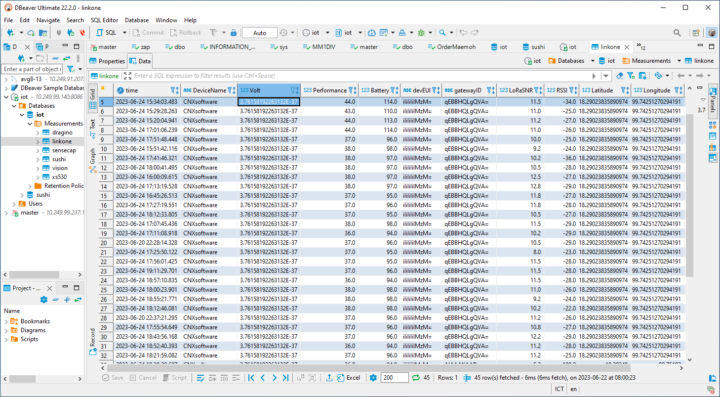
Node-RED also automatically stores sensor and LoRaWAN system data in the InfluxDB time-series database.
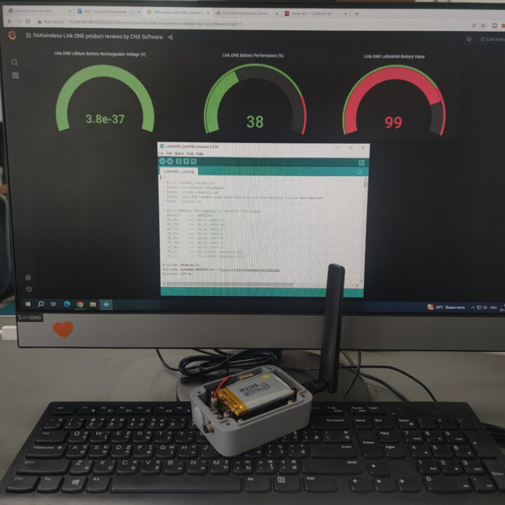
The Grafana dashboard reads data from the InfluxDB time series database and displays the results with the battery voltage, the battery level in percent, and the power consumption in mW while the data is being transmitted.
Finally, the LINE Notify application monitors the lithium battery voltage, and if it drops below 3.3 Volts, an alert/notification will be sent to the LINE application to let us know immediately.
Conclusion
The WisTrio Link.ONE development kit is suitable for IoT device developers who are interested in assembling various sensors, writing code for versatility, and connecting to various wireless low-power wide area networks (LPWAN) such as LTE-M, NB-IoT, and LoRaWAN. Compatibility with the Arduino IDE makes it very easy to use. The Monogoto SIM card is also an advantage with a 500 MB data package that can be used for up to 10 years. That’s provided it works in your country.
We’d like to thank RAKwireless for sending us a Link.ONE development kit for review. RAKwireless sells the Link.ONE all-in-one LPWAN development kit for as low as $56, but if you’d like the WisBlock Unify Enclosure with a battery, the total would be $107. We’d also recommend getting one or more sensors with the kit. The company warns that adding a battery increases the delivery costs, so if possible, you might want to source it locally.
CNXSoft: This article is a translation of the original tutorial in Thai on CNX Software Thailand by Ninephon Kongangkab.

Jean-Luc started CNX Software in 2010 as a part-time endeavor, before quitting his job as a software engineering manager, and starting to write daily news, and reviews full time later in 2011.
Support CNX Software! Donate via cryptocurrencies, become a Patron on Patreon, or purchase goods on Amazon or Aliexpress


