Karl here. Today let’s look at the Atezr V35 35W diode laser engraver. Atezr is new to the market, at least I am just becoming aware of them, and they asked for a review of one of their machines. This fell in line with the laser power meter project I have been working on, so I accepted, hoping to further along that progress. My goal is to validate the 35W power spec.
First, this is 35W optical power….not just the power consumed. You have to be very careful today when shopping for laser engravers. I hate this trend where manufacturers are highlighting total power consumption in marketing materials. This spec is prominently shown in an attempt to trick the consumer into thinking the laser is more powerful than they are.
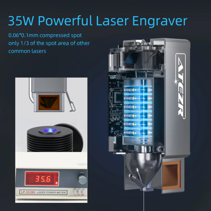
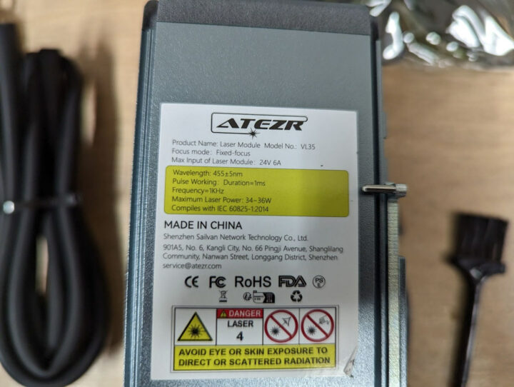
Until starting this review I thought the optical power limit for a single diode laser was 5.5W. I asked Atezr about this and yes they are using 6W diodes. I don’t know if it is the linked diode. They would not share the part number. Another trend is that multiple vendors are combining multiple diode lasers into one single beam assembly like Atezr allowing for the combining of power diodes. The V35 uses six 6W lasers for a combined power of 35W. I assume Atezr went the safe route and marketed the laser engraver to 35W to allow for some diode variance. Xtool is the only other vendor with a larger module. But that looks only to be available as an upgrade. I think it is OK to say the V35 is the most powerful diode full laser kit readily available.
Back to combining lasers. This does not seem trivial to do. I would have to imagine that at least some of this has to be tuned by hand.
Let’s wade through the marketing and get the highlights. The full specs can be found on the product page.
- Engraving Size – 430 x 430mm
- Laser power – 35W
- 455nm laser
- Dimensions – 644 x 680 x 168mm
- Integrated air assist pump
- Lightburn compatible
Here are the logs from unboxing, assembly, and first impressions.
April 25 – Atzer V35 assembly
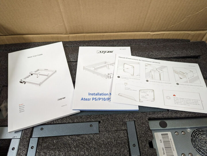
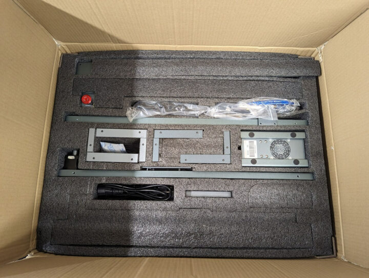
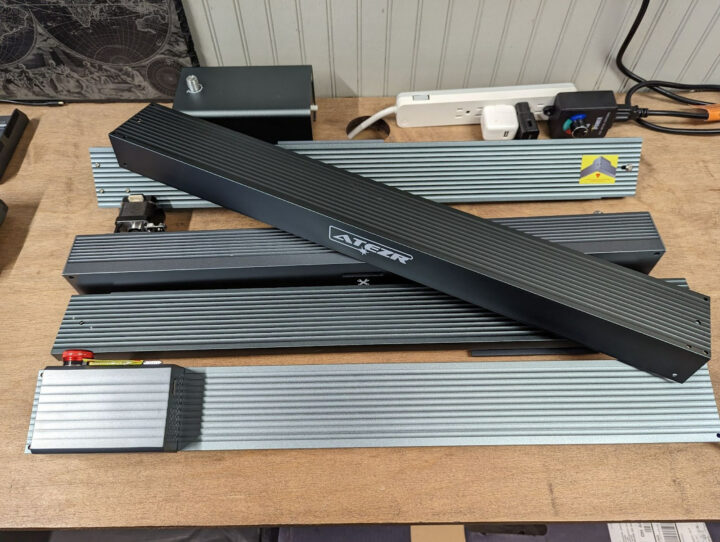
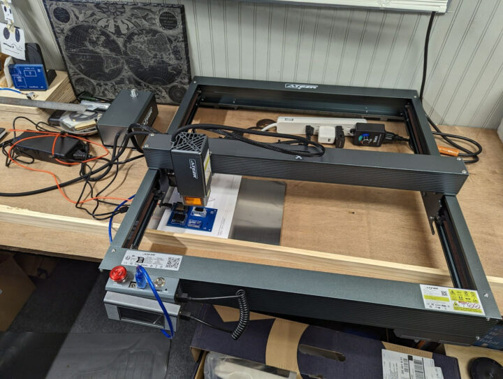
First night. Just got done. Everything went pretty smoothly. Unboxed and built the 35W laser cutter/engraver. The instructions are pretty good. Even went into talking about tensioning belts. Screws were nicely bagged and labeled by steps. Overall build seems good. I see one potential issue with the motion system. The rod that joins the left and right side belts might be a little undersized. The rod does not resist torsion very well. This should be easy to test.
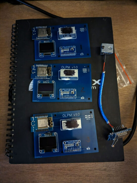
I have been working nonstop the past weeks continuing on with a laser power meter. Now I understand why no one has pursued this. I think I have made some real progress and am excited and nervous to test against the Atezr V35. I’m still honing in the calibration process and have it calibrated to 20W against another machine.
April 26 – Fixing some small issues
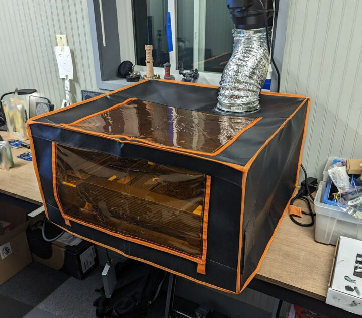
Short night. I couldn’t ignore the torsion issue. It was nothing. My fingers didn’t feel the twisting in the coupler last night. After using the short end of the Allen key and tightening the coupler the issue was gone. But then that is where I ran into an issue of space. The V35 is just slightly bigger than my 24” bench can accommodate. I have an enclosure I built long ago in the shed for a 3D printer. I am going to pull it out this weekend. On hold for a few days until I can move it from my outbuilding. I am glad the Atezr has offline capability.
One last thing: the display was not staying on straight. I spent a few minutes in a meeting today and opened it up. 4 screws and a plastic prying tool and it was open. There are 4 magnets and 1 was out of place. I was surprised to see the magnets with no apparent glue to hold them in place. I didn’t add any glue and put it back together. It took about 5 minutes.
May 1 – Fusion 360 and 3D printing legs for the workbench
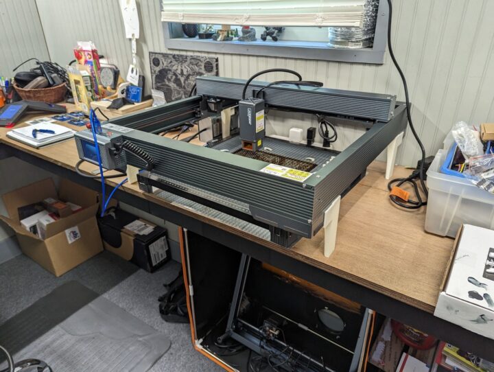
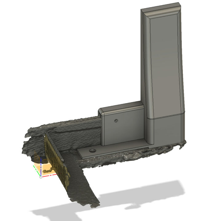
If any time a year is the rainy season it is now. I wasn’t able to bring the box in from my shed due to the rain. I dove into Fusion 360 and used Creality’s Lizard scanner to model some legs to 3D print so I can use my workbench. Got that done and printed one pair as a prototype.
May 2 – Quick tests
I tested out the prototype first thing and the legs worked well enough. My bench is 24” deep. I started the second half after testing and all of the legs were done by lunch today. It took a few minutes and everything was tidy. This enclosure is the same as previous laser endeavors.
I will be away the rest of the week so I went after what I thought was low-hanging fruits by testing the laser power meter. Tests are inconclusive. I had to monitor the USB port to capture the G-code to turn on the laser. My old batch file didn’t work. Got the batch file working with this machine. But in the process messed up my COM ports from all the software I had to test to find one that worked. I got it resolved. I will pick back up next week with a quick project.
May 8 – First laser engraving with Atzer V35
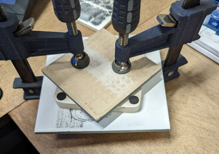
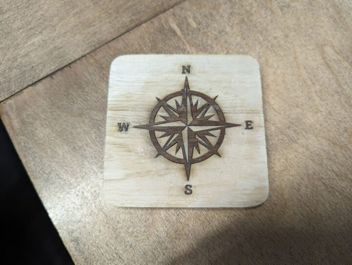
Back from a little vacation, I wanted to try to do a little project tonight. So I started with a coaster with an inlay. It took me a few tries to get the fit right but it should turn out good. I ended up cutting with no kerf. The inlay was 3 mm thick with some very small details that with a perfect fit I would not be able to get in. I did both a -.1 and .1 offset. Will let dry until morning then a light sand and clearcoat. I had to clamp it because it was popping back out after relieving pressure. I went a little crazy with wood glue. I am hoping the staining of the wood is only on the surface. One thing I did observe was the glue sorta acted like a lubricant. Next time I will add a slight kerf offset. I will have to see once dried and sanded. The S is the only one that looks a little loose.
- Engrave 9000 mm/min 100 2.5 passes.
- Cut 600 mm/min 90
- No kerf offset
Power Meter
I kept at the power meter for the next month. I squashed 1 bad software bug, fixed the data sent to the serial port for future analysis, readability, and testing different algorithms. I tested out adding a shroud to alleviate heat loss by the fans in the diode laser module. And on and on. But I could not get consistent results across two machines.
I needed more data. I found someone doing a power test with a calibrated meter for several machines. What I can glean from this and apply to my experiences is that power rating can be both above and below spec which is problematic. If I calibrate the meter to 35 Watts when in fact the laser is outputting 33 watts it will mess with the calibration process and vice versa. Additionally, the two machines I am working with are not the same wavelength. 445nm vs 455nm. On professional meters, they do account for the wavelength….I am not sure what impact this has.
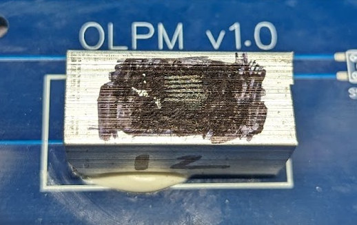
This makes for a very symmetrical laser point.
Every other machine I have used so far has not been symmetrical.
I am wrapping this up and identified a few variables I need to eliminate in the future. I have spent way too long on this and burning out.
First I need to ensure the aluminum is absorbing all the energy. I have been using a Sharpie to darken the aluminum and can see the Sharpie coloring is damaged. I am assuming some energy is being reflected.
Finally, I need to test increasing the mass of the aluminum that is being heated up. My original logic is that a bigger temperature rise would result in more accuracy. But that may be misguided in retrospect. My aluminum pieces are only 12g and getting about 20 deg rise in temperature with the V35 over 10 seconds.
Safety
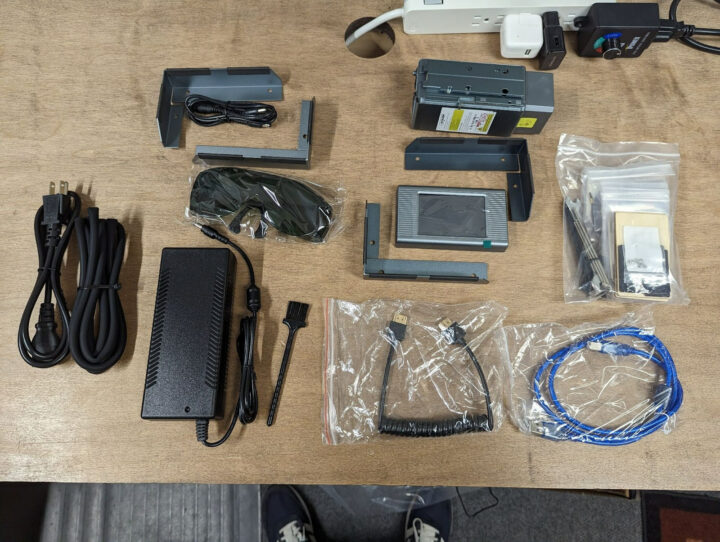
I try to include something about safety in every review. I am torn regarding enclosures. I think every kit needs one but it feels wrong to say it should be required to be included in every kit for plenty of reasons. I can only say there needs to be unity in this messaging both from the community and manufacturing. The manufacturers should unify and stress the importance of an enclosure and safety which leads to the included “safety” glasses. I am not an expert but the universal consensus is that typically the included glasses are inadequate. Stay safe.
Wrap up
The machine is really nice looking and I like the departure from the basic 2020 aluminum extrusion motion system with plastic pulley wheels. But at its core….this is just nicer looking 2020 extrusion. This is not a jab…it’s a proven motion system with thousands if not millions of 3D printers using it.
My only real complaint is the lack of support to adjust the height of the frame. If they would have put two strategically placed holes in the included feet, they could be rotated and used and get a little over 100mm in height added. I was going to modify to raise mine but I also had to address my desk depth. The other complaint is the cooling fan….it is always on. Why?
Unfortunately, I cannot answer my own question fully. Is the laser 35W? But I have strong evidence that it is very close. I think this laser meter project is on hold until I can come up with a power meter to calibrate off of.
If you would like to pick up an Atezr V35 laser engraver on Amazon it is currently discounted to $1599 or you can purchase it directly on Atezr’s website for significant savings and currently available for $1,150.

Karl is a technology enthusiast that contributes reviews of TV boxes, 3D printers, and other gadgets for makers.
Support CNX Software! Donate via cryptocurrencies, become a Patron on Patreon, or purchase goods on Amazon or Aliexpress




For thermal power sensing I don’t think there should be much difference between 445nm and 455nm. Commercial sensors based on photodiodes (ie not thermal) have a quantum efficiency which is strongly dependent on wavelength, so they need a correction factor to account for this. But as long as you have a strongly absorbing surface, for thermal testing the wavelength doesn’t matter too much over such a small range.
The surface treatment of your absorbing target is very important, you need to reduce the specular reflections (ie the “shininess”) as much as possible. Creating a coating which is able to withstand the laser power while fully absorbing/transferring the heat and not degrading is the true “secret sauce” part of these sensors.
If I were to attempt testing the power, first I would test the LED input power, and factor that with the luminous efficiency from the LED manufacturer. That will provide a halo number, hopefully significantly higher than the claimed 35W.
If the claimed power is lower than the halo, then next I would measure the kJ absorbed by a black body.
Fill a narrow diameter test tube half full with water and a dark ink, shine the laser down the middle (probably need to use a lens to diverge the beam a bit) and measure the time it takes to achieve a 10C temperature rise. Use the mass of the water and half the test tube.
That will give you a kWh number lower than the true power output, but if the dye is sufficiently opaque it should be close, and then you can calibrate to results from another known laser.
The deception of saying that a laser is 80 Watts when it’s actually just 10 or 15 is really gross. I knew something was up when I was seeing lasers from Western advertisers and they all say 10 or 20 and then you look at Eastern advertisers and they all say 40 or 80.
If you like I did fell for this initially, the way to get them to reverse it and to not charge you for the shipping of the return is to threaten to report them to the bank as a fraudulent company because that actually affects them, and they don’t want it.
That is a good reference point. I had a service related issue with one of the “big named” Chinese printer mfgs. The equipment is highly regarded. There service is very poor. They promised a refund, however, it tools weeks and lots of emails while finally reporting them to my CC banking institution. Suddenly, the refund was provided with the CC institution stating they might challenge the refund. After 8 weeks I received notification that a full refund had been agreed to! Buyer beware. They make great products but they are a few centuries behind in quality of service.
With specific heat of Al =0.9J/g-K I’m getting about 22W for your power rating. This is ignoring losses to the environment so the real wattage will be somewhat higher.
I build a somewhat hackish optical power measurement tool. I attached together a large resistor, a diode and a black anodized aluminum plate inside a polystyrene foam box. I aim the laser at it and wait for the voltage across the diode to stabilize, indicating the plate has (and components) finished heating and the laser compensates losses into the environment. Then I stop the laser and send power into the resistor, adjusting it to end up on the same value across the diode. Once I find it, I note the voltage and current across the resistor, which is 100% thermal power, corresponding to the laser’s optical power. Of course this only works for multi-watt lasers and needs to be done quickly so that environmental conditions do not change, but it allowed me to measure around 5.5W for my single diode “NEJE 30W” which is supposed to reach 7.5W in pulses, this seems correct.