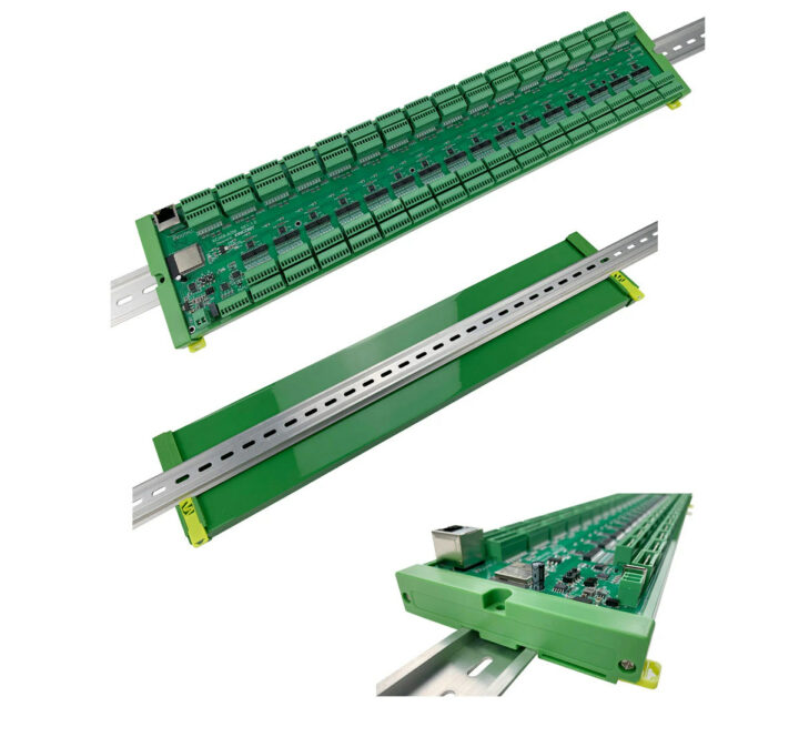
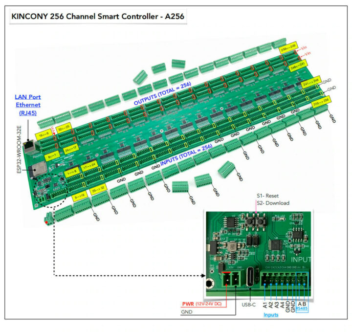
KinCony IoT’s KC868-A566 is an ESP32 WiFi & BLE IoT board with a massive 512 GPIOs, more specifically with 256 12V/24V digital outputs and 256 digital inputs that should meet most people’s requirements, except for its price, as it is currently selling for $1,000 on Aliexpress.
The board is based on ESP32-WROOM-32E, and besides the massive numbers of GPIOs, also adds four analog input ports, an Ethernet port, and an RS485 connector. The company also made sure it can run ESPHome open-source firmware and integrates well with Home Assistant open-source home automation framework.
KinCony IoT KC868-A566 board specifications:
- Wireless module – ESP32-WROOM-32E with
- ESP32 dual-core microcontroller
- 4MB flash
- 2.4 GHz WiFi and Bluetooth LE connectivity, built-in PCB antenna, fully compatible with ESPHome firmware
- Ethernet – 100/10Mbps Ethernet via vertical RJ45 jack
- USB – 1x USB Type-C port
- Serial – RS485 interface
- I/Os
- 256x MOSFET outputs (12V/24V 5000mA per channel) with 74HC595 serial to parallel chips
- 256x dry contact inputs with 74HC165 chips
- R485 and 4x analog inputs (2x 0-5V DC, 2x 4-20 mA) on 8-pin terminal
- Misc – LED for each GPIO, 2x buttons (Reset and Download)
- Power Supply – 12 to 24V via 2-pin terminal
- Dimensions – 505 x 105 mm; support for DIN Rail mounting
The company says you can program the board with your own Arduino source code for DIY home automation projects, but it also runs ESPHome or Tasmota for easy integration with Home Assistant as demonstrated in the video below. There’s also a support forum for all their KC868 controllers, and they are quite active on YouTube as well releasing about two videos per week about their products.
When thinking more about it, the $1,000 price tag for an ESP32 board with 512 GPIOs may not be that excessive because that’s less than $2 per I/Os, and could be useful to automate your house, factory, hotel, hospital, airport, etc…
Via Hackster.io

Jean-Luc started CNX Software in 2010 as a part-time endeavor, before quitting his job as a software engineering manager, and starting to write daily news, and reviews full time later in 2011.
Support CNX Software! Donate via cryptocurrencies, become a Patron on Patreon, or purchase goods on Amazon or Aliexpress


“less than $2 per I/Os” OK. ESP32 has 34 GPIO pins and costs 11.50 euro plus 6.50 euro for terminal block adapter. That’s 18 euro. Even if you use only 18 pins and the rest are for serial comm or whatever, that’s 1 euro per I/O pin. And you don’t have to put all the control wiring in one place.
This thing is terminally overpriced.
My interest vanished when I read “74HC595 serial to parallel chips”
You could use any kind of AVR or other cheap micro instead…
74 logic is just dead in such use cases. From many many years. It was dead before the ESP arrived.
And the ESP is definitely not the uC of choice for such a project, too few native IOs, too much latency due to dozens of IO expanders, not to even talk about glitches.
Why even use a ESP32 at this point?
There are much better microcontrollers that have a lot more GPIO. They aren’t as cheap as a ESP32 but it doesn’t seem like price is an issue at this point…
Or maybe even use a FPGA.
Why even use the ESP32? Because it beats just about everything out there, and you have no idea what your talking about. With That many GPIO’s it has nothing to do with how many I/O lines the micro has.
You are the one who doesn’t know what you are talking about. The ESP32 is nice but it has a number of issues.
A lot of those aren’t an issue when you consider the price diference and that you get some really nice stuff like Wifi and BT(and those from TI/Renesas/STM lack it completely).
For this project, as it’s a very expensive one, it would likely be just far better to get a big MCU with many GPIO lines, you will probably still have to mux them a bit, but probably like 1:4 or 1:2 at most.
This looks quite professional with features that are missing from most boards. Removable connectors and LED indicators make it a lot more serviceable.
For something “professional”, its totally lacking any useful documentation.
It looks like it was a special for someone, rather than an off the shelf product you can buy.
They have a portfolio of architecturally similar boards, and the lack of useful documentation is common for all.
Personally I would not use a board like this. The single point of failure is too large. I’d go with multiple boards. Probably 16 boards of 32 instead. With the smaller boards you can afford to keep a spare around. Also consider the effort needed to swap this monster out.
Well just use a proper PLC…
Maybe not AB or Siemens but a cheaper one like Wago or Ingeteam…
And forget about proper tests and certifs if you go with this here.
Btw how many Arduino Uno clones do you get for 1000$? Ok add 24V IO shields to the wishlist too…
If you’re going to need 1024 I/O’s, using distributed I/O’s makes much more sense.
And it’s going to be one huge wiring mess. Let’s say I want to hook up 512 Omron photoelectric sensors: I am going to need 512 power connections, 512 ground connections, and 512 inputs (1536 total wires), but this ONLY provides 1 ground per every 8 inputs, I’ll only have 576 wires going to this, and 960 wires to deal with elsewhere.
Many smart homes these days contain a single hub for all smart appliances. There might also be a router / switch for something like 48 or 96 ethernet ports for 10 Gbps ethernet / SFP+. You need multiple miles of cables, but smart homes are designed for the richer part of the audience.
I don’t know why builders do all of those home runs to the basement. I stopped mine from running miles of wiring and had him put in two small cabinets on each floor. I am vertically oriented and have four flours.. About ten nearby jacks run to each of those cabinets – Ethernet, phone, cable. Each cabinet has an Eero and a switch in it. I only hook up the jacks that I need active. Finally each of the small cabinets has a home run to the basement. This saved massive amounts of wiring. He was going to do home runs for every single jack before I stopped him.
I would not call this 512 GPIOs:
Generic issues
The inputs seem to be optically isolated (look at the bottom picture, and compare with e.g. the KC868-A16), but I can not spot an isolated current source for the opto-couplers. It also means only mechanical switches will likely work.
About the price, both HC595 and HC165 are at 0.30€@100, i.e. 4 cent per port. Optocouplers are ~15 cent per channel, output transistors are about the same. Add some resistors etc, and you are at about 40…60 cent per port.
IMHO this all boils down to – if this board provides exactly what you need, i.e. 256 optically isolated inputs, 256 open-drain transistor outputs, then it is okay. For most of the cases it is just a huge pile of compromises.
Amazing board .. it is not for home automation only..
Useful to automate your house, factory, hotel, hospital, airport, etc…
Powerful output ports that can drive a load of 12/24V 5000mAmps per channels.. No need for relays…
I hope it won’t generate too much of the famous electric smoke…
256x5A = 1280A…
> No need for relays…
LOL. Ever heard of galvanic isolation, AC, or voltages above 24V?
Using this for medical applications? What could go wrong …
Each MOSFET on the board will dissipate 2..5W @ 5A, apparently they forgot to mention the “glow in the dark” feature.
It has no documentation, no certification, and is horribly overpriced.
I once made my own home controller: https://github.com/AMBRACE-BV/CiiiXo
Because lack of time the software isn’t finished yet but for hobbyist with a bit of software knowledge it shouldn’t be a problem. It does the same as the KC868 but expandable (distributed) which makes it easier to wire with multiple ground and 24 connections on the pluggable connectors.