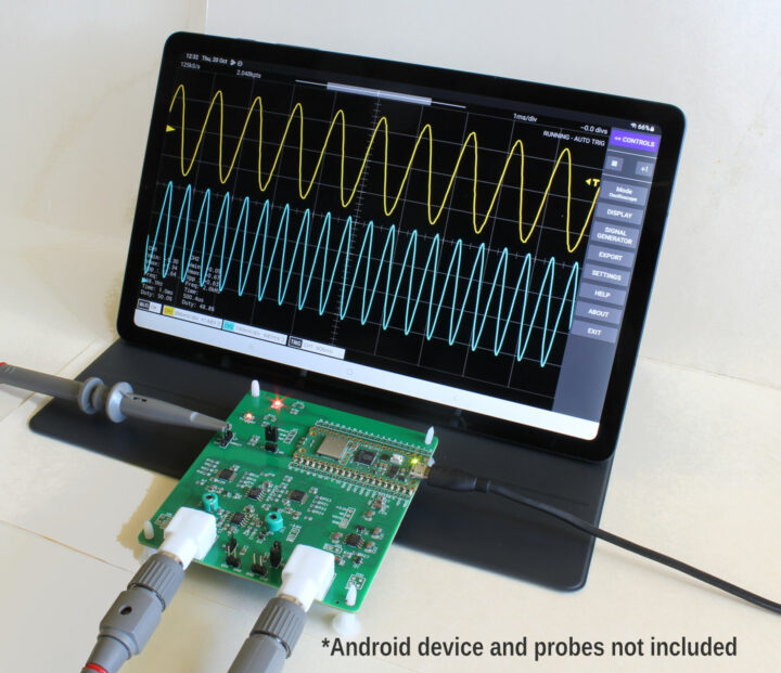
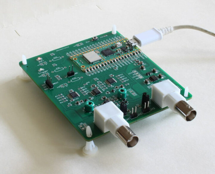
FHDM TECH DSO-500K is a 2-channel 500kS/s WiFi oscilloscope based on Raspberry Pi Pico W board that can also work over USB, and offers an analog bandwidth of up to 150kHz.
We previously had seen the Raspberry Pi Pico board used as a logic analyzer, so it should come as no surprise that somebody has also come up with a Raspberry Pi Pico W-based oscilloscope that enabled visualization on Android over WiFi or USB.
DSO-500K specifications and features (through the Scoppy app):
- MCU board – Raspberry Pi Pico W board with RP2040 dual-core Cortex-M0+ microcontroller, 2MB SPI flash, WiFi 4 and Bluetooth connectivity
- Sample rate – Up to 500kS/s sample rate (250kS/s with both channels enabled)
- Analog bandwidth – 150kHz
- Record length – 2048 samples per channel in RUN mode, 100kS total for single shot captures
- Inputs – BNC connectors or 0.1-inch headers
- Input Impedance – 1MΩ / 22pF
- Input voltage range – Up to +/- 6V (1X probes), +/- 20V (10X probes)
- Coupling – AC/DC
- Host connectivity – WiFi or USB (OTG)
- Misc – Indicator LEDs: Status, Wi-Fi and Trigger
- Display Modes – YT, FFT, FFT+YT, X-Y, X-Y+YT
- Trigger Types – Rising edge/falling edge
- Trigger Modes – Auto/Normal (Run Mode + Single captures)
- Cursors: YT and FFT horizontal and vertical cursors
- On-screen measurements – Vmin, Vmax, Vpp, Frequency, Period, Duty
- Snapshot measurements (screen or sample record): Mean, DC RMS, AC RMS
- FFT Window functions: Hann, Hamming, Blackman, Rectangle
- FFT Vertical units: dBm, dBmV, V
- Export data format: CSV
- Other functions
- Signal generator – square wave up to 1.25MHz, sine wave – 1kHz
- Logic Analyser – 25MS/s (requires soldering extra headers to the board – not supplied). No protocol decoding as yet.

You can find the Scoppy firmware and instructions to get started on the documentation website, and the Scoppy app on Google Play. The source code for the firmware and mobile app has not been released, but the project’s GitHub repository has some information about both and schematics in PNG format.
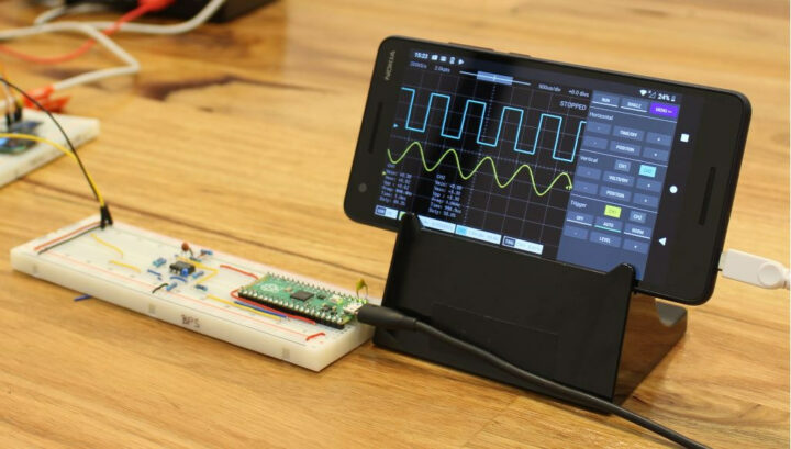
You don’t even need the DSO-500K oscilloscope to experiment with Scoppy, as the firmware can be installed on a Raspberry Pi Pico or Pico W and a basic circuit made on a breadboard or a perfboard. Having said that, the DSO-500K should be easier to get started and includes a free upgrade to the premium version of the Scoppy Android app.

This solution reminds me of the Ikascope W200 WiFi pen-oscilloscope I reviewed a few years ago with Android and Ubuntu with a wider analog bandwidth (30 MHz) and sample rate (200 MSps), but it sells for around 249 Euros right, and the FHDM TECH DSO-500K WiFi oscilloscope can’t be beaten on price as it is offered for $33.50 plus shipping with a Raspberry Pi Pico W soldered on the board.

Jean-Luc started CNX Software in 2010 as a part-time endeavor, before quitting his job as a software engineering manager, and starting to write daily news, and reviews full time later in 2011.
Support CNX Software! Donate via cryptocurrencies, become a Patron on Patreon, or purchase goods on Amazon or Aliexpress


In my opinion, nowadays to be useful an oscilloscope suppose to have at least 3-4 MHz analog bandwidth – DC/DC converters etc.
You’re not wrong. You should always have more BW than you think you’ll need. Mostly because people don’t really appreciate how BW works in the first place. I remember back in college when my CprE colleagues would complain how the signals on the scope looked all rounded off even though it was ‘just’ a 50MHz square wave and the scope was upposed to be a 100MHz BW one. You could hear the EE students roll their eyes.
I don’t remember who it was, perhaps Dave from EEVblog, but some engineer said that you should always plan to have 4 times the bandwidth of whatever it is you’re trying to measure.
For digital signals, you want over 5x or you’re going to see a lot of ringing and other artifacts that aren’t really there in the real signal. Square waves are not band limited signals.
And, yeah, that sounds like Dave.
One of the cheaper ways to get a Pico-W….
It’s a cool project but bandwidth only for middling audio these days. Perhaps as a logic analyzer for classic Atmel chips?