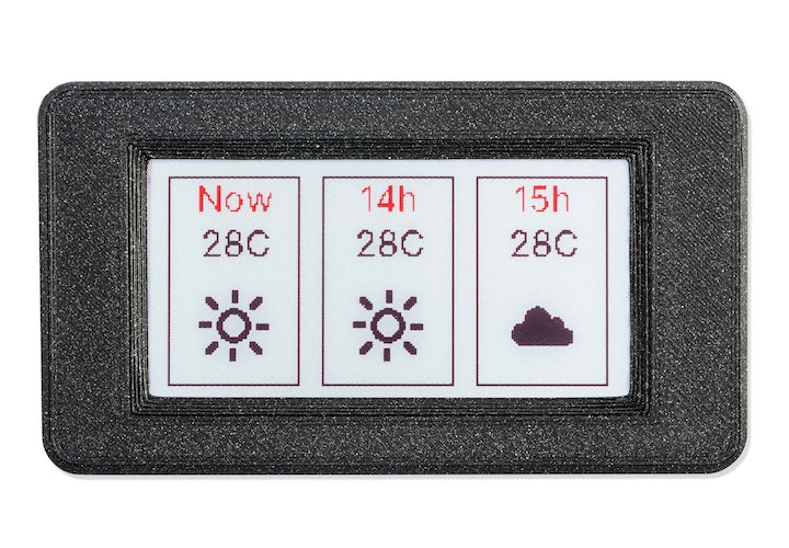
Inkplate 2 wireless ePaper display is by far the smallest display from Soldered Electronics with a 2.13-inch 3-color ePaper display while previous Inkplate models rely on 6-inch to 9.7-inch ePaper displays.
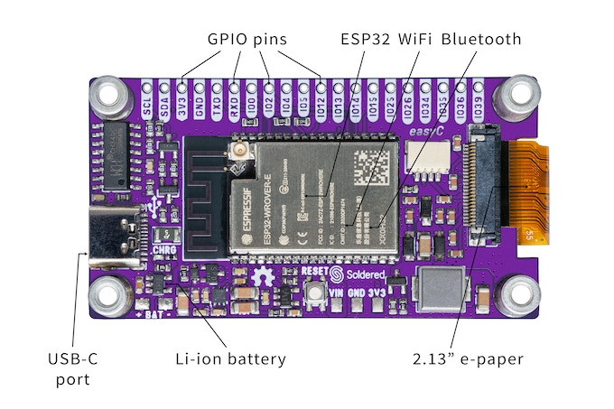
The tiny display board integrates an ESP32 dual-core wireless microcontroller that drives the display, provides WiFi and Bluetooth connectivity plus some I/Os, and can be programmed with the Arduino IDE or MicroPython.
Inkplate 2 specifications:
- Wireless module – ESP32-WROVER-E module with ESP32 dual-core microcontroller with Wi-Fi 4 & Bluetooth 4.0 connectivity, 8MB PSRAM, 4MB flash (Note: The product’s description lists 8MB flash, and 4MB RAM, but there’s no ESP32-WROVER-E in this configuration)
- Antenna- External IPX antenna
- Display – 2.13-inch ePaper display with
- 212×104 resolution (111 DPI)
- Red, black, and white colors
- 15 seconds full refresh time (no partial update)
- USB – 1x USB Type-C port for power and programming via CH340 USB to TLL chip
- Expansion
- 20-pin header with GPIOs, I2C, UART, 3.3V and GND
- easyC I2C connector compatible with the Qwiic connector
- Power Supply
- 5V via USB Type-C port
- Solder pads for Li-ion battery, MCP73831 charger IC
- Power Consumption – 8uA
- Dimensions – 65.2 x 35.3 mm
The InkPlate 2 is mostly designed to be programmed in the Arduino IDE using the Inkplate library itself based on the Adafruit GFX library, and with several code samples albeit none of which are specifically designed for the 2.13-inch wireless display at this time. There are two other ways to control the display either with MicroPython or using the board as a peripheral receiving UART commands from a host microcontroller to update the display. All displays will ship with the “peripheral mode” firmware. Finally, Soldered Electronics also provides a web-based GUI editor, which has yet to be updated to support the Inkplate 2. The full documentation for all Inkplate displays can be accessed on the Readthedocs website.
e-Radionica and Soldered Electronics used to introduce their displays on Crowd Supply, but the Inkplate 2 was launched on Kickstarter instead. The project has already surpassed its $10,000 funding target with close to $30,000 raised so far. Rewards start at $35 for the Inkplate 2 board, but you could also pledge $55 for a kit that adds an enclosure and a battery. Expected shipping costs are $12 within the European Union, $15 for the USA, and $19 for the rest of the world. Deliveries are scheduled to start in March 2023.
Via Hackster.io

Jean-Luc started CNX Software in 2010 as a part-time endeavor, before quitting his job as a software engineering manager, and starting to write daily news, and reviews full time later in 2011.
Support CNX Software! Donate via cryptocurrencies, become a Patron on Patreon, or purchase goods on Amazon or Aliexpress


Oh, look, someone put the antenna right in the middle of a ground plane–again. *facepalm*
Yup, it’s not hard to follow the placement guidelines.. it’s like the want to have poor signal quality..
It seems to stem from a lack of experience, but that can be concerning for the rest of the device that is not that easily visible.
I feel like I need to offer a design review service for projects like this. Maybe find a few other people with PCB layout experience and provide design feedback to projects like this. I wonder if Bunny would want to organize an effort like that. I think I’ll mention it to him.
They’ve done those ESP32 displays at least since 2019.
https://www.cnx-software.com/?s=inkplate&post_type=post
All boards seem to have the same design “issue”. I guess they did not get complaints.
I stand corrected, I can see a cutout for the antenna in the Inkplate 6Color. https://www.cnx-software.com/2022/02/10/inkplate-6color-5-8-inch-e-paper-color-wireless-display/
That’s not enough spacing. Take a look at Chapter 3 of esp32_hardware_design_guidelines_en.pdf. You can either hang the antenna portion of the module off the PCB entirely (no PCB below the modules and no ground plane under/beside/above/around either. Or you can put it on the edge of the board with a 15mm ‘keep away’ distance for the front and sides of the antenna portion of the module. You may have ground under the non-antenna portion of the module.
There are some other suggestions in that section as well. But, if you’re not using the onboard antenna, you can put the module anywhere you want.
Okay, did a lot of reading and I think I found something critical. In the datsheet for the ESP32-WROVER-IE, it shows the schematics for the E and IE variants. In the E variant, the resistor to select the PCB antenna is populated and the one heading to the IPX is not populated. In the IE variant, it’s the other way around which means the IE version, while it may have a PCB antenna on the board, *cannot* use the PCB antenna. An external antenna *must* be supplied.
That seems to be an important thing to note here. The presence of that PCB antenna is quite misleading, IMHO.
That was alo my first thought. But in the description they mention an “External IPX antenna” so i think the pcb antenna is not used.
Erm, since you can buy a universal esp32 Bluetooth, wireless epaper driver for waveshare and 2.13 inch colour epaper displays are both common on Aliexpress, for less.
Why?
Honestly, in all but the photoshopped images, the quality does NOT look good.
There are a bajillion tiny e-ink thingies out there now–why do we need another one? The 6″ and 10″ are at least interesting. A new one should have been 14″ and not 2″.
Looks like the one that fell on my foot in aldi just before, unfortunately I couldn’t remember the fcc id