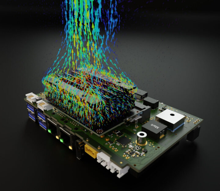
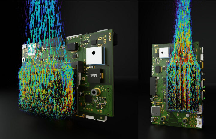
code_saturne is a free, open-source computational fluid dynamics (CFD) software developed primarily by EDF that can be useful to check and optimize the thermal design of your projects.
From time to time, we come across hardware platforms that do not perform to their best due to overheating leading to CPU throttling, and over time it may also impact the lifetime of the device. I’ve heard about computational fluid dynamics (CFD) before, but I always assumed the software was prohibitively expensive and Formula 1 even has a cost cap for CFD testing. But it turns out there’s an open-source program to do just that: code_saturne.

As a utility company, EDF designed the software to simulate the flows around and inside the buildings, pipes, and pumps used in power plants, but Lukas Henkel found out he could also use the free and open-source code_saturne program for analyzing the air currents caused by natural convection around a heatsink. Other tools to create the visualization above include ParaView and blender 3D both of which are also open-source.
This could probably be used to select a specific heatsink, but Lukas notes that the orientation of the cooling is also critical in order to achieve the best possible performance:
The performance of a passive cooling assembly can vary by more than 50% depending on the orientation of the heatsink. This is usually true for linear extrusion heatsinks as the main cooling features are all aligned along a single axis.

If you want to give it a try you’ll find source code, documentation, tutorials, and a support forum on the project’s website. The code is portable and it has worked on on all Linux flavors and UNIX platforms tested by the company so far. It can also run in parallel with MPI on distributed memory machines (Intel, Cray X series, IBM Power, …). There’s probably a steep learning curve to achieve what Lukas did, but if it may be worth it you’re regularly involved in the thermal design of electronic products. You can watch what code_saturne open-source CFD program is capable of – from EDF’s perspective – in the video below. The YouTube channel also has a few tutorials.

Jean-Luc started CNX Software in 2010 as a part-time endeavor, before quitting his job as a software engineering manager, and starting to write daily news, and reviews full time later in 2011.
Support CNX Software! Donate via cryptocurrencies, become a Patron on Patreon, or purchase goods on Amazon or Aliexpress


Very interesting, particularly if it starts to be used by SBC vendors 😉 At least it confirms the general intuition that the heat sink’s fins must be placed vertically to allow the hot air to flow up along them and take some heat with it. I have attached some boards vertically next to a shelf for this reason 😉
> heat sink’s fins must be placed vertically to allow the hot air to flow up along them and take some heat with it
But this only works somehow if the distance between heatsink fins is large enough (the displayed Jetson heatsink is a good example for appropriate spacing) and the whole thing is not cramped into an enclosure too small.
Also there’s no real need to simulate airflow when you also can simply measure/graph SoC temperature in different scenarios to somewhat confirm ‘general intuition’. 🙂
> But this only works somehow if the distance between heatsink fins is large enough
Absolutely. For example I have this on my build farm, I can insert my little finger between the fins. For another one I’m having 2-3 mm spacing between fins and that’s fine. Amusingly it’s easy to spot if ins are spaced enough. Placing your hand above the heat sink in its final position, you should feel some heat form convection, otherwise it doesn’t work.
Regarding the ability to measure, I was really referring to SBC vendors who could try to improve v1 of their design and place components smartly. If the initial design is poor due to some components hindering air flow or hiding each other (e.g. NVME SSD on top of SoC), you know that a significant fix can be required that’s not necessarily easy to deal with. Trying a better modeling of the initial expected design first at a low cost can help choose between various placement options.
The basic small arm SBC is just equivalent to a low power GPU laid flat, for cooling purposes. Effective solutions for cooling are out there, but old out moded beliefs just stick a high volt PC fan and heatsink, on for cooling.
I’ve been informed about other open-source CFD (or similar) programs that could be useful:
OpenFoam(finite volume)
https://www.openfoam.com/
Fenics(finite element)
https://fenicsproject.org/
Freefem++(finite element)
https://freefem.org/
SU2
https://su2code.github.io/
Wondering how much power its distributed execution will draw, to be mostly dissipated as heat …