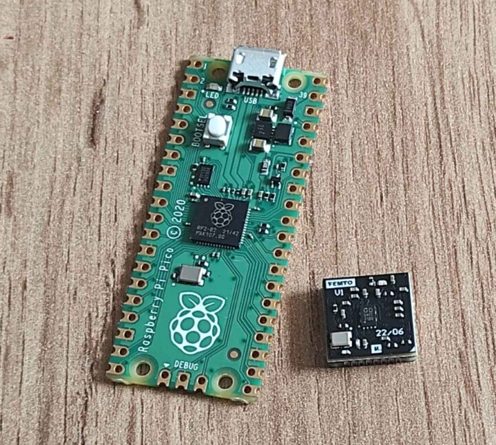
Mirek Folejewski has designed the ridiculously tiny Femto module based on the Raspberry Pi RP2040 microcontroller with a size of just 12x12mm, and still including an SPI flash, a crystal, and a few passive components.
We’ve previously covered some really tiny RP2040 boards with the Pimoroni Tiny 2040 and Adafruit QT Py RP2040 boards, as well as the RP2040 Stamp module, but the 12x12mm Femto module is about a quarter of the size of 25x25mm RP2040 Stamp.
Femto specifications:
- MCU – Raspberry Pi RP2040 dual-core Cortex-M0+ microcontroller @ up to 133Mhz with 264kB of SRAM
- Storage – 4 to 64Mbit QSPI flash
- I/O – 30 GPIO pins, Reset and BOOTSEL signals, etc… exposed through a frame (See below)
- Misc – Status LED, 12MHz crystal oscillator, decoupling capacitors
- Dimensions – 12 x 12mm
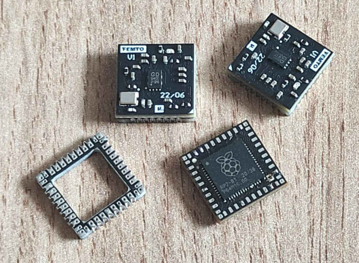
The board is comprised of two parts: the module itself (aka mainboard) with the Raspberry Pi RP2040 microcontroller and the frame (aka solder frame) exposing the I/Os in a somewhat usable way.
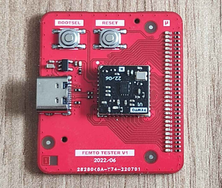
But since the Femto is so small, Mirek also designed a tester to test the module. It comes with LEDs to test the GPIOs, a USB Type-C port for power and programming, as well as the BOOTSEL and Reset buttons.
The Femto board is open-source hardware with the KiCAD and Altium design files (schematics, PCB layout) plus manufacturing files, the bill-of-materials, etc… available on Github where you’ll also find a Python script to tet all 30 GPIOs, as well as some extra photos.
It’s unclear whether the module will ever be manufactured in quantities and sold, or whether it was just a project for kicks-and-giggles, as although it looks neat, I’m not sure as to who exactly needs this.
Via Hackster.io

Jean-Luc started CNX Software in 2010 as a part-time endeavor, before quitting his job as a software engineering manager, and starting to write daily news, and reviews full time later in 2011.
Support CNX Software! Donate via cryptocurrencies, become a Patron on Patreon, or purchase goods on Amazon or Aliexpress


I initially thought that they had designed a PLCC-socket compatible Pi-Pico. Rather interesting that the “solder frame” is used as an interposer for a “dead-bug” module – but can you truly call an upside-down SMT module “dead-bug”?
Please wrote something about that.:
https://www.leapfive.com/en/?page_id=4173
What?
Very smart idea! I’m not completely sure it willl succeed because for such original ideas to work, there needs to be some demand to create a trend, but this probably offers one of the highest possible densities while remaining compatible with a wide range of tiny devices. Usually the alternative is to place the devices vertically but then you lose lots of I/Os; on such a size you could at best have half of it (i.e. two independent rows at the same density).
Not bad but instead let’s convince rpi foundation to make a package with all those components inside like esp32 pico which is 7mmx7mm
I think it’s great! I object strongly when the community is forked or large amounts of labor are spent on stuff that doesn’t matter, but people who know what they are doing like this guy can design this sort of thing in a few days, and have them made by custom pcb manufactures. If the source is out anyone can’t make one of these.
So, although I am the first to complain about yet another board when we need work on the existing ones, this is still good because the work that goes into the drivers and micropython port and so on is still compatible.
Ideal for those “modchip” uses for the Pico 😉