CNXSoft: This getting started guide/review of the SenseCAP K1100 sensor prototype kit is a translation of the original post on CNX Software Thai. The first part of this tutorial describes the kit and shows how to program it with Arduino to get sensor data to a LoRAWAN gateway and display it on Wio Terminal, before processing the data in a private LoRaWAN network using open-source tools such as Grafana. The second part – to be published later – will demonstrate the AI capability of the kit.
In the digital era where IoT and big data are more prevalent, a large amount of data is required to be collected through sensors. To enable the digital transformation, SeeedStudio’s SenseCAP K1100 comes with all necessary sensors and equipment including the Wio Terminal, AI Vision Sensor, and a LoRaWAN module. With this plug-and-play platform, makers can easily create DIY sensors for data collection and solve real-world challenges.
Let’s define some terms first:
IoT stands for “Internet of Things” and refers to the network of devices connected to the Internet. It allows us to control the use of various devices through the Internet such as turning on-off devices, electrical appliances, cars, mobile phones, communication tools, agricultural equipment, buildings, houses, and even home appliances that we use daily.
LoRaWAN is an acronym for “Long Range Wide Area Network”, a radio technology based on the LoRa protocol designed for ultra-low-power long-distance communications. It is becoming more and more popular among IoT developers, such as connecting smart devices.
SenseCAP K1100: Designed by Seeed Studio, it is a compact Sensor Prototype Kit with LoRaWAN and AI designed to help developers and makers create IoT prototypes. The Wio Terminal supports Wi-Fi and Bluetooth wireless communication only, but LoRaWAN connectivity can be added through with the Grove LoRa-E5 Module part of this kit. In this review, we will focus on sensor data gathering through a private LoRaWAN network.
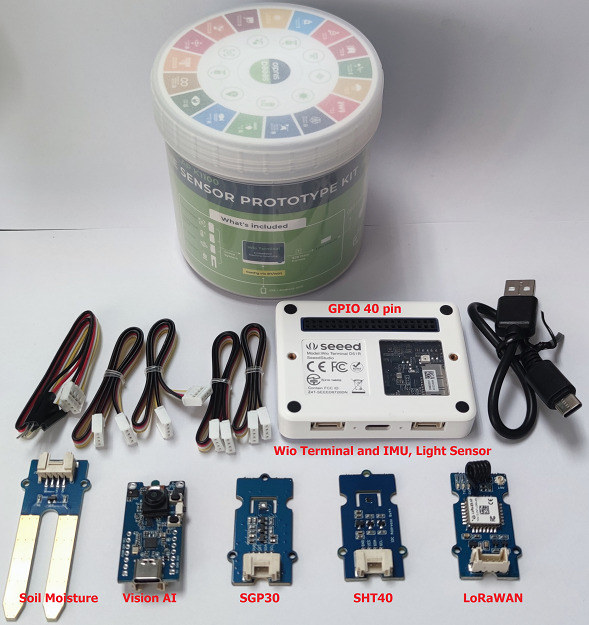
Content of the SenseCAP K1100 kit
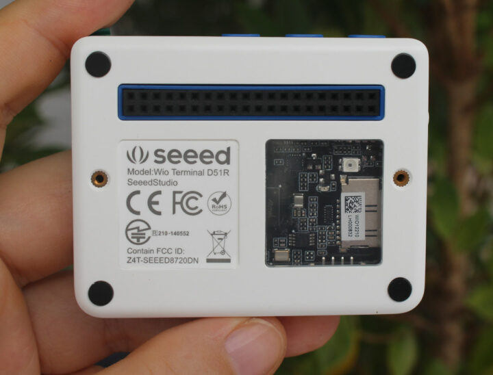
Wio Terminal, an Arduino-compatible HMI controller with WiFi and Bluetooth.
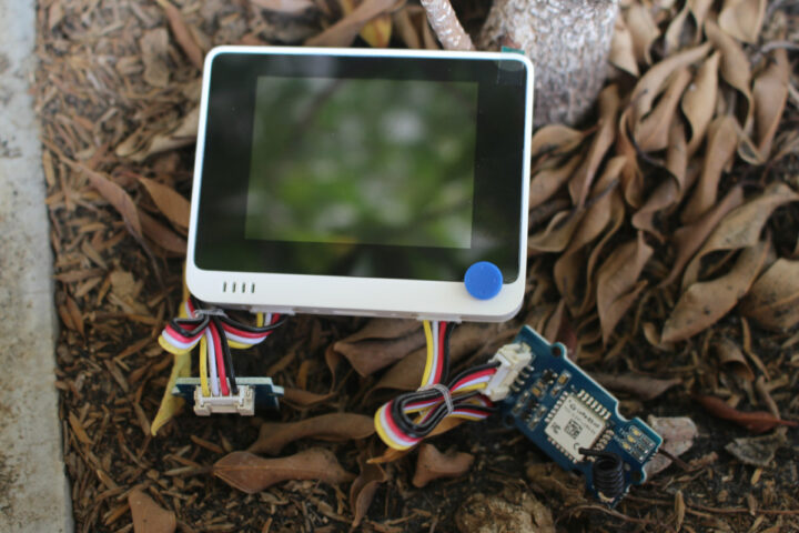
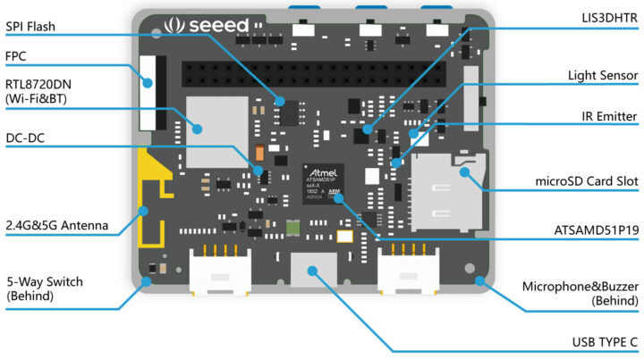
Wio Terminal specifications:
- MCU – Microchip ATSAMD51P19 Arm Cortex-M4F running at 120 MHz
- Wi-Fi & Bluetooth – Realtek RTL8720DN Arm Cortex-M4 microcontroller with dual-band (2.4 GHz and 5 GHz) WiFi.
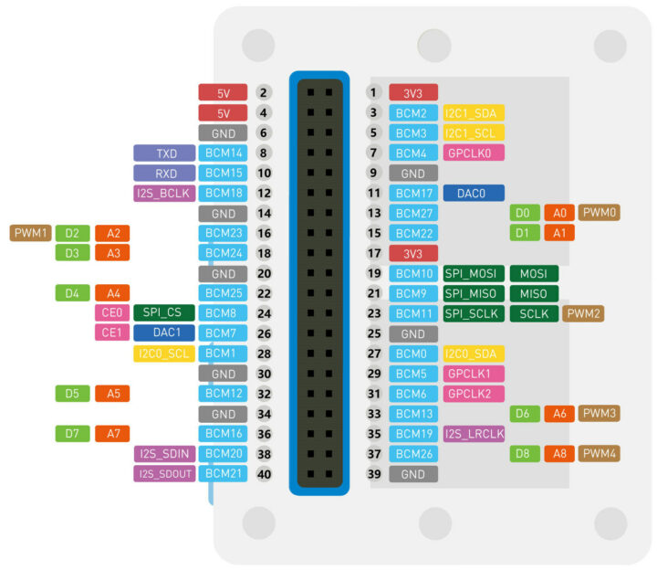
- GPIO – 40 pin, same pin position as Raspberry Pi
- On-board sensors and features
- On board 3-axis digital accelerometer (LIS3DHTR)
- Light sensor
- Microphone & buzzer
- IR emitter
- 2.4-inch LCD Screen
- TinyML (AI and Machine Learning) support
- LoRa-E5 LoRaWAN module based on STM32WLE5JC MCU; RF power: +20.8 dBm, supports EU868/US915/AU915/AS923/KR920 frequency bands.
- SHT40 temperature and humidity sensor module
- SGP30 module acting as air quality sensor (VOC and eCO2 Gas Sensor)
- Soil moisture module
- Vision AI module with camera
Working Principle of the SenseCAP K1100 sensors
The light sensor uses a photoelectric as a sensing element. It converts the changes in the measured light into an electrical signal.
The temperature sensor relies on the thermocouple method. It consists of 2 metal wires forming an electrical junction. A thermocouple produces a temperature-dependent voltage as a result of the Seebeck effect, and this voltage can be interpreted to measure temperature.
The relative humidity sensor measures the humidity through a polyamine film or acetate polymer. When the film absorbs or loses water, the dielectric constant changes between the two electrodes, and the capacitance can be recorded & converted into electrical signals.
Getting started with SenseCAP K1100
Requirements
We’ll need the following our getting to measure environmental data and send it to our private LoRaWAN network:
- Wio Terminal
- USB Type-C cable
- LoRa-E5 module
- SHT40 module
- A host computer
- A LoRaWAN Gateway
- A LoRaWAN Cloud Platform
Hardware connection
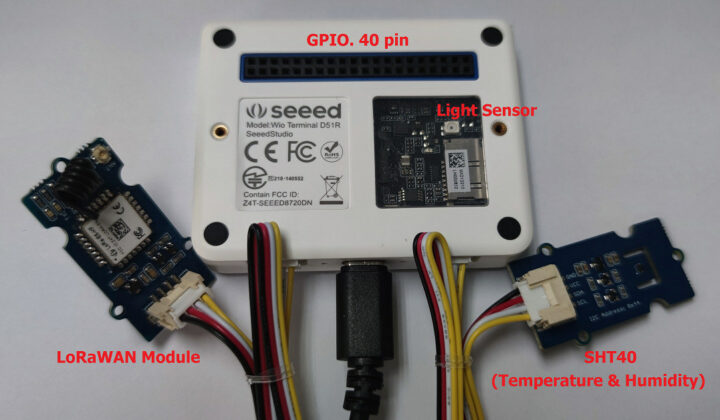
Let’s try to use SenseCAP K1100 by connecting the SHT40 sensor module to measure the air temperature and relative humidity, as well as the light and sound values from the sensor and microphone built into Wio Terminal, then connect the board to a LoRaWAN gateway using the LoRa-E5 module.
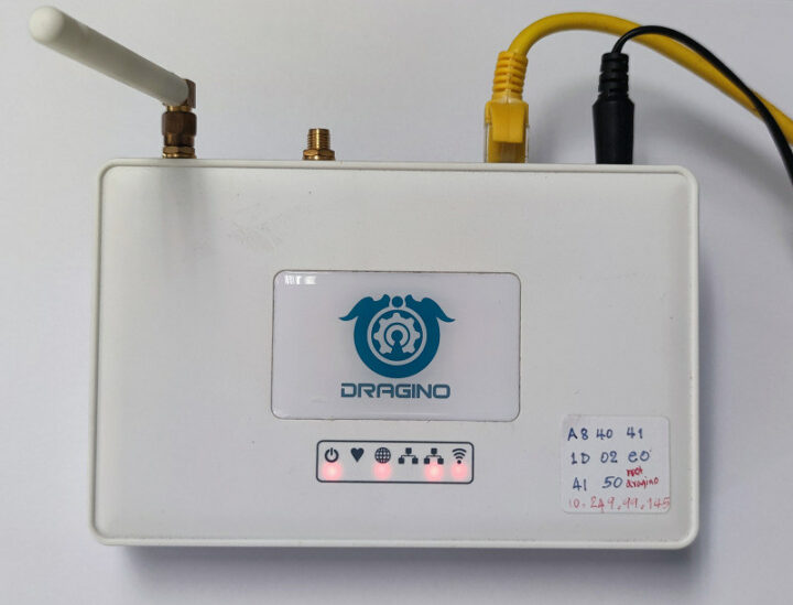
We’ll also use the Dragino LG308-AS923-TH-EC25 multi-channel LoRaWAN gateway with a 4G LTE internet connection.
Software installation and instructions
Here are the step to follow for the software part
- Install the Arduino IDE
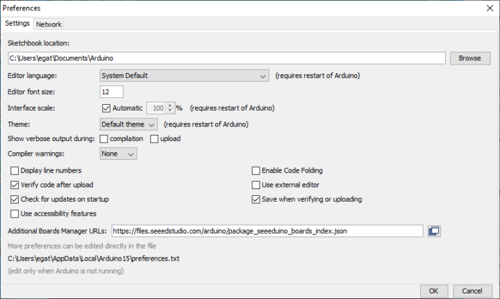
- Add the board file required for Wio Terminal. In the Arduino top menu, go tp File -> Preferences and copy/paste https://files.seeedstudio.com/arduino/package_seeeduino_boards_index.json inro the Additional Boards Manager URLs box:
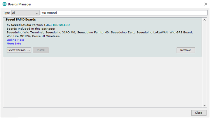
- Click on Tools -> Board -> Board Manager and search for Wio Terminal.
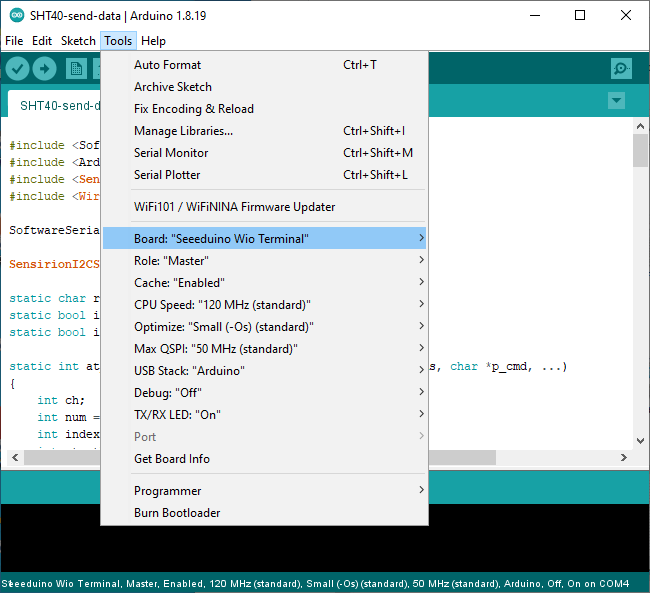
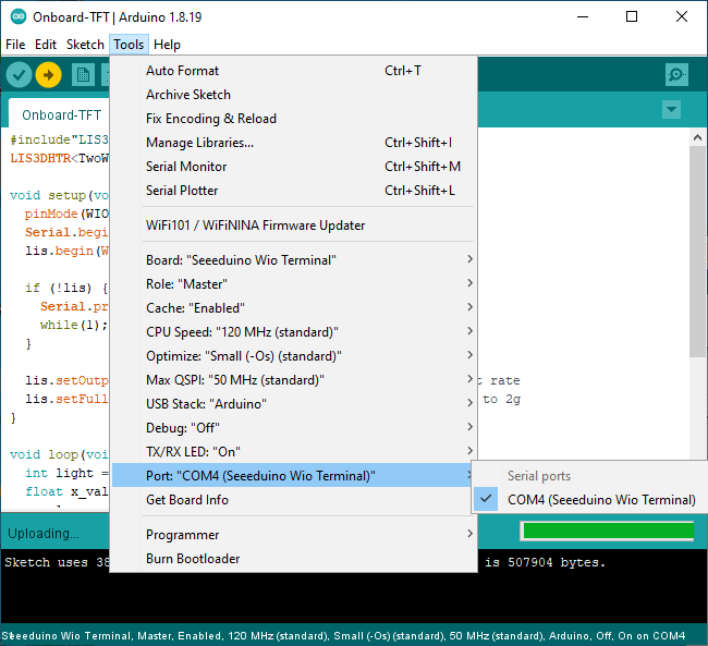
- Now go to Tools -> Board and select the board Seeeduino Wio Terminal
- Add the Arduino library for the SHT40 temperature and humidity sensor. Download the file arduino-i2c-sht4x.zip, then go to Sketch -> Include Library -> Add .ZIP Library and select arduino-i2c-sht4x
- Add the LoRa-E5 Arduino library in the same manner after downloading Disk91_LoRaE5.zip
- Add Seeed Arduino LCD library at Seeed_Arduino_LCD.zip
- We’ve then modified the code of the LoRa-SHT40-TFT.ino sample to adapt it to our environment, and display the information on Wio Terminal display:
123456789101112131415161718192021222324252627282930313233343536373839404142434445464748495051525354555657585960616263646566676869707172737475767778798081828384858687888990919293949596979899100101102103104105106107108109110111112113114115116117118119120121122123124125126127128129130131132133134135136137138139140141142143144145146147148149150151152153154155156157158159160161162163164165166167168169170171172173174175176177178179180181182183184185186187188189190191192193194195196197198199200201202203204205206207208209210211212213214215216217218219220221222223224225226227228229230// LoRaWAN + SHT40 + Light + Microphone + TFT LCD// by.. Ninephon kongangkab <ninephon9@gmail.com>#include <SoftwareSerial.h>#include <Arduino.h>#include <SensirionI2CSht4x.h> //SHT40 library#include <Wire.h>#include "TFT_eSPI.h" //TFT LCD libraryTFT_eSPI tft; //Initializing TFT LCDTFT_eSprite spr = TFT_eSprite(&tft); //Initializing bufferSoftwareSerial mySerial(A0, A1); // RX, TXSensirionI2CSht4x sht4x;static char recv_buf[512];static bool is_exist = false;static bool is_join = false;static int at_send_check_response(char *p_ack, int timeout_ms, char *p_cmd, ...){int ch;int num = 0;int index = 0;int startMillis = 0;va_list args;memset(recv_buf, 0, sizeof(recv_buf));va_start(args, p_cmd);mySerial.printf(p_cmd, args);Serial.printf(p_cmd, args);va_end(args);delay(200);startMillis = millis();if (p_ack == NULL){return 0;}do{while (mySerial.available() > 0){ch = mySerial.read();recv_buf[index++] = ch;Serial.print((char)ch);delay(2);}if (strstr(recv_buf, p_ack) != NULL){return 1;}} while (millis() - startMillis < timeout_ms);return 0;}static void recv_prase(char *p_msg){if (p_msg == NULL){return;}char *p_start = NULL;int data = 0;int rssi = 0;int snr = 0;p_start = strstr(p_msg, "RX");if (p_start && (1 == sscanf(p_start, "RX: \"%d\"\r\n", &data))){Serial.println(data);}p_start = strstr(p_msg, "RSSI");if (p_start && (1 == sscanf(p_start, "RSSI %d,", &rssi))){Serial.println(rssi);}p_start = strstr(p_msg, "SNR");if (p_start && (1 == sscanf(p_start, "SNR %d", &snr))){Serial.println(snr);}}void setup(void){Serial.begin(115200);mySerial.begin(9600);Wire.begin();tft.begin(); //Start TFT LCDtft.setRotation(3); //Set TFT LCD rotationspr.createSprite(TFT_HEIGHT, TFT_WIDTH); //Create bufferpinMode(WIO_LIGHT, INPUT); //Set light sensor pin as INPUTpinMode(WIO_MIC, INPUT); //Set Microphone sensor pin as INPUTuint16_t error;char errorMessage[256];sht4x.begin(Wire);uint32_t serialNumber;error = sht4x.serialNumber(serialNumber);delay(5000);if (error) {Serial.print("Error trying to execute serialNumber(): ");errorToString(error, errorMessage, 256);Serial.println(errorMessage);} else {Serial.print("Serial Number: ");Serial.println(serialNumber);}Serial.print("E5 LORAWAN TEST\r\n");if (at_send_check_response("+AT: OK", 100, "AT\r\n")){is_exist = true;at_send_check_response("+ID: DevEui", 1000, "AT+ID=DevEui,\"xxxxxxxxxxxxxxxx\"\r\n");at_send_check_response("+ID: AppEui", 1000, "AT+ID=AppEui,\"xxxxxxxxxxxxxxxx\"\r\n");at_send_check_response("+MODE: LWOTAA", 1000, "AT+MODE=LWOTAA\r\n");at_send_check_response("+DR: AS923", 1000, "AT+DR=AS923\r\n");at_send_check_response("+CH: NUM", 1000, "AT+CH=NUM,0-2\r\n");at_send_check_response("+KEY: APPKEY", 1000, "AT+KEY=APPKEY,\"xxxxxxxxxxxxxxxxxxxxxxxxxxxxxxxx\"\r\n");at_send_check_response("+CLASS: A", 1000, "AT+CLASS=A\r\n");at_send_check_response("+PORT: 8", 1000, "AT+PORT=8\r\n");delay(200);is_join = true;}else{is_exist = false;Serial.print("No E5 module found.\r\n");}}void loop(void) {uint16_t error;float temperature, humidity;int int_temp, int_humi;error = sht4x.measureHighPrecision(temperature, humidity);int_temp = temperature * 100;int_humi = humidity * 100;int light = analogRead(WIO_LIGHT); //Assign variable to store light sensor valuesint mic = (analogRead(WIO_MIC))/10; //Assign variable to store microphone sensor values//Setting the title headerspr.fillSprite(TFT_WHITE); //Fill background with white colorspr.fillRect(0, 0, 320, 50, TFT_DARKGREEN); //Rectangle fill with dark greenspr.setTextColor(TFT_WHITE); //Setting text colorspr.setTextSize(3); //Setting text sizespr.drawString("CNX Software", 50, 15); //Drawing a text stringspr.drawFastVLine(150, 50, 190, TFT_DARKGREEN); //Drawing verticle linespr.drawFastHLine(0, 140, 320, TFT_DARKGREEN); //Drawing horizontal line//Setting Temperaturespr.setTextColor(TFT_BLACK);spr.setTextSize(2);spr.drawString("Temperature", 10, 65);spr.setTextSize(3);spr.drawNumber(temperature, 50, 95); //Display Temperature valuesspr.drawString("C", 90, 95);//Setting Humidityspr.setTextSize(2);spr.drawString("Humidity", 25, 160);spr.setTextSize(3);spr.drawNumber(humidity, 30, 190); //Display Humidity valuesspr.drawString("%RH", 70, 190);//Setting Microphonespr.setTextSize(2);spr.drawString("Microphone", 180, 65);spr.setTextSize(3);spr.drawNumber(mic, 205, 95); //Display microphone valuesspr.drawString("dB", 245, 95);//Setting lightspr.setTextSize(2);spr.drawString("Light", 200, 160);spr.setTextSize(3);light = map(light, 0, 1023, 0, 100); //Map sensor valuesspr.drawNumber(light, 205, 190); //Display sensor values as percentagespr.drawString("%", 245, 190);spr.pushSprite(0, 0); //Push to LCDif (is_exist) {int ret = 0;if (is_join) {ret = at_send_check_response("+JOIN: Network joined", 12000, "AT+JOIN\r\n");if (ret) {is_join = false;}else {Serial.println("");Serial.print("JOIN failed!\r\n\r\n");delay(5000);}}else {char cmd[128];sprintf(cmd, "AT+CMSGHEX=\"%04X %04X %04X %04X\"\r\n", int_temp, int_humi, light, mic);ret = at_send_check_response("Done", 10000, cmd);if (ret) {Serial.print("Temperature: "); Serial.print(temperature);Serial.println();Serial.print("Humidity: "); Serial.println(humidity);Serial.print("Light: "); Serial.println(light);Serial.print("Microphone: "); Serial.println(mic);recv_prase(recv_buf);}else {Serial.print("Send failed!\r\n\r\n");}delay(5000);}}else{delay(1000);}} - You’ll also need to edit the program to set the required information for the LoRaWAN board as follows:
- DevEUI number (8 bytes)
- AppEUI number (8 bytes)
- APPKEY number (16 bytes)
- Set up an OTAA connection
- Specify the working frequency band. For example, it is AS923 in Thailand is AS923
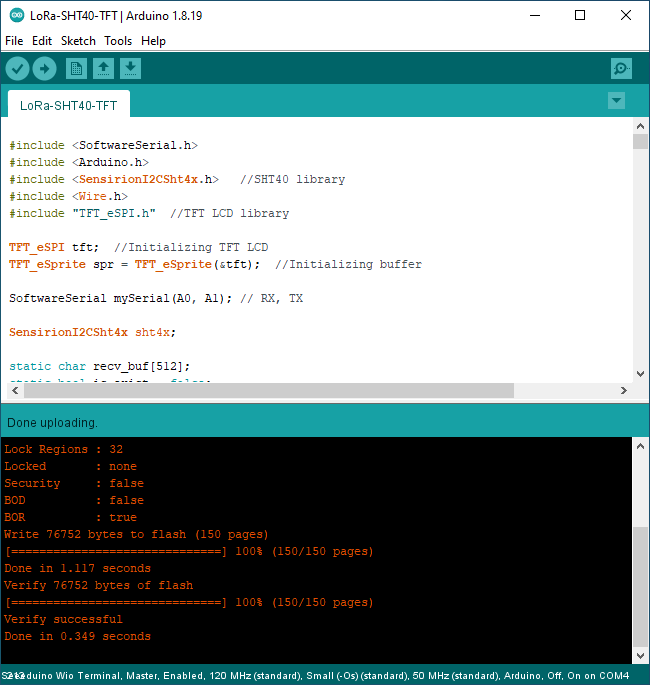
- Upload the program to the board Wio Terminal. One advantage of this board is that it will automatically enter Bootloader mode, and we do not need to press any buttons.
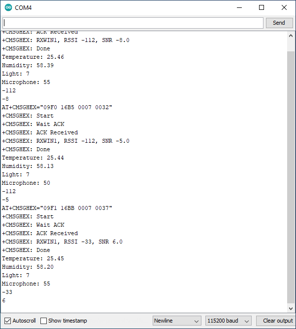
- Open the Serial Monitor to check out the output from the program. If everything works as expected, it will show where the LoRaWAN connection is successful and values from the sensors, for instance: Temperature = 25.46 degree , Humidity = 58.39% , Light = 7 % and Microphone = 55 dB.
- We can also check out the sensor data displayed on the Wio Terminal controller
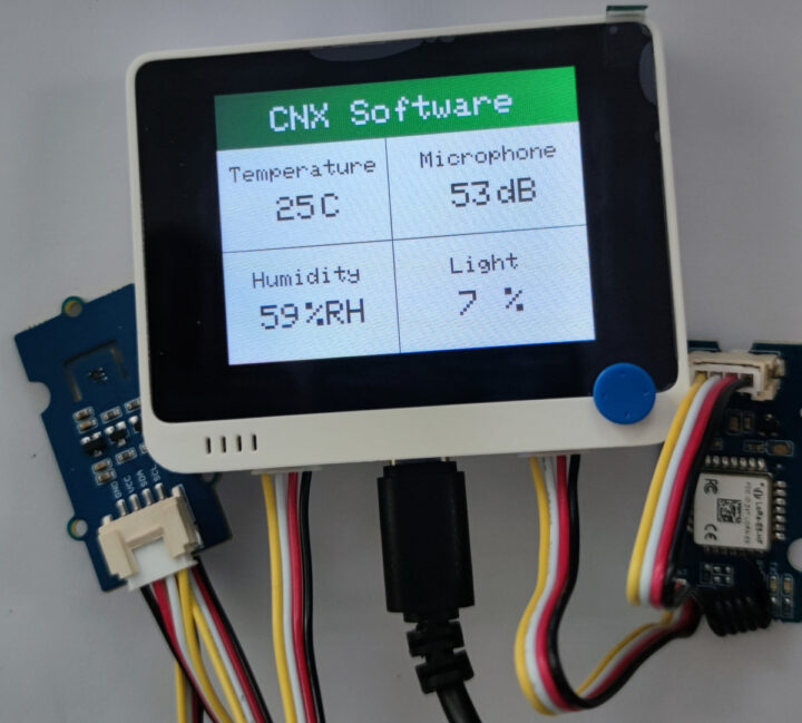
After the Wio Terminal board reads the value from the sensor, it is re-encoded in AES-128 (Advanced Encryption Standard) format and transmitted wirelessly through the LoRa-E5 Module. If it is within range of the LoRaWAN gateway, the data will then be forwarded to the LoRaWAN network, and we’ll have a look at that shortly. In the meantime, here’s a short video demo of the data being updated on the display.
A small hiccup while programming Wio Terminal
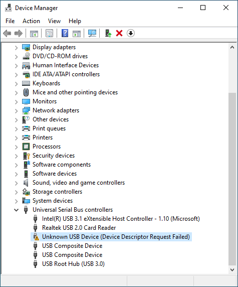
At some point, I had an issue during the review while trying the flash the program to Wio Terminal via the Arduino IDE. The uploading part would be stuck forever…
… because the computer would not recognize the Wio Terminal with an error reading “unknown USB Device (Device Descriptor Request Failed)” as shown in the picture below.
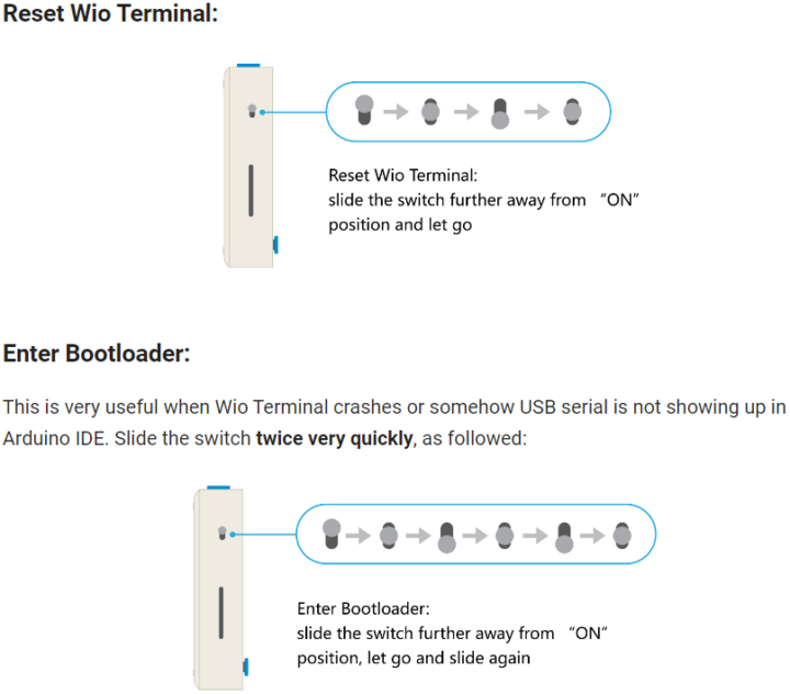
Even though I tried to reset the board and enter the Bootloader manually many times, I was not successful while trying the method in the illustration below.
So we decided to contact Seeed Studio to help us with the issue, but their technical support just provided the same answer. It turns out the keywords are “twice very quickly“, and initially I pressed the button twice, relatively fast, but not quite enough. Sliding the switch repeatedly, I was able to use the Wio Terminal again. (I can’t count how many times I tried!). That means the computer can see the USB port again and we could continue the review with everything working normally. The important takeaway is that if the board hangs, you need to enter the Bootloader mode manually.
Private LoRaWAN IoT on-premise platform
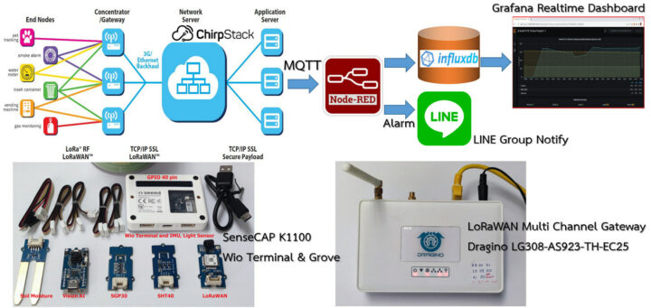
Now that we’ve got data from the SenseCAP K1100 kit sent to our gateway we’ll process it through a private LoRaWAN IoT Platform I have installed for personal use. It is based on various software open-source components as explained below:
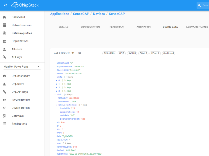
- ChirpStack open-source LoRaWAN network and application server that registers the LoRaWAN IoT device number and decrypts the received data in AES128 format through an MQTT broker (Message Queuing Telemetry Transport) acting as the sender (publish).
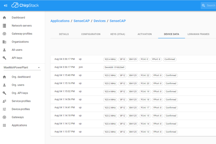
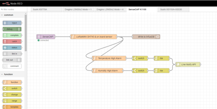
- Node-RED flow-based development tool for programming. It is a recipient (subscribe) from ChirpStack via the MQTT protocol and takes the data from the payload and decodes it according to the BASE64 format. It will store the sensor data in an InfluxDB database, and check and configure notification settings in the LINE Notify Application.
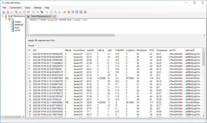
- InfluxDB is an open-source time series database that stores sensor and LoRaWAN gateway data, and automatically sorts it by time series allowing us to analyze the data for any period of time.
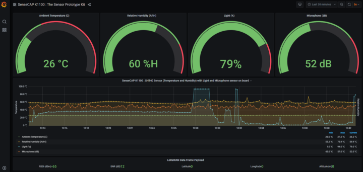
- We also use Grafana real-time dashboard to visualize the data from the InfluxDB database.
- LINE Notify: When the sensor is higher or lower than a specified value, the LINE messaging application will notify us via the LINE Notify API only once, meaning there will be no notification for duplicate values.
Final words: Who is SenseCAP K1100 suitable for?
The SenseCAP K1100 sensor prototype kit is suitable for pupils, students, and experimenters (makers) who want to create prototypes with various sensors, write code (Arduino), and test proof-of-concept (PoC) using a LoRaWAN a wireless connection. However, for more practical applications, industrial-grade sensors are more suitable and reliable. Those are also available from Seeed Studio and other vendors.
I would like to thank Seeed Studio for sending the SenseCAP K1100 sensor prototype kit for this review. It is available for $99.00 plus shipping.
Continue reading “AI, computer vision meet LoRaWAN with SenseCAP K1100 sensor prototype kit“.

Jean-Luc started CNX Software in 2010 as a part-time endeavor, before quitting his job as a software engineering manager, and starting to write daily news, and reviews full time later in 2011.
Support CNX Software! Donate via cryptocurrencies, become a Patron on Patreon, or purchase goods on Amazon or Aliexpress







Hello, You also need to include Sensirion Core – Arduino Libraries