M.2 sockets are typically used to connect wireless or storage expansion boards to laptops, computers, and SBC’s. But nothing precludes them from being used for another purpose, and earlier this year we wrote about Sparkfun MicroMod MCU boards with an M.2 connector for GPIOs, I2C, SPI, etc…
IZITRON has expanded the concept with three slightly larger (IZIRUN) STM32 boards routing more IOs to the M.2 connector, and additional features such as built-in EEPROM and buttons. IZIGOBOARD carrier board is then used to host the STM32F0, STM32F4, or STM32F7 board in order to ease development.
IZIRUN STM32 development boards
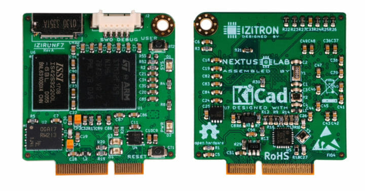
IZIRUN boards specifications:
- Microcontroller
- IZIRUNF0 – STMicro STM32F030CCT6 Cortex-M0 MCU @ 48 MHz with 256KB flash, 32 KB SRAM
- IZIRUNF4 – STMicro STM32F407VET6 Cortex-M4 MCU @ 168 MHz with 512KB flash, 192KB SRAM
- IZIRUNF7 – STMicro STM32F769NIH6 Cortex-M7 MCU @ 216 MHz with 2MB KB flash, 532KB SRAM
- On-board RAM – IZIRUNF7 only – 8MB SDRAM
- Storage
- 16KB EEPROM
- IZRUNF0/4 – 512KB flash
- IZIRUNF7 – 2MB flash plus MicroSD card socket
- I/Os via M.2 socket with 67-pin
- Up to 4x UART, up to 2x I2C, 1x SPI, up to 4x ADC, up to 21 PWM
- Up to 43 GPIOs (23 GPIO max for IZIRUNF0)
- IZIRUNF4/7 only
- CAN Bus via on-board Microchip ATA6561 CAN FD-ready transceiver
- 10/100M Ethernet via on-board Microchip LAN8742A PHY
- IZIRUNF4 only – USB device
- IZIRUNF7 only
- USB OTG
- MIPI DSI
- 2x DFSDM (Digital Filter for Sigma-Delta Modulator), a generic ADC
- Misc – Reset and user buttons, SWD debug port
- Dimensions – 35 × 35 mm
- Temperature range – -20°C to +80°C
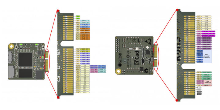
IZIRUNF0 is designed for low-power applications and IoT projects, IZIRUNF4 for motor control, display (matrix, OLED), CAN, Ethernet communications, etc…, while the IZIRUNF7 board can be used for more complex applications with 2D accelerated graphical user interfaces, audio, Ethernet, and more.
IZIGOBOARD carrier board
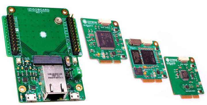
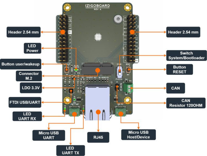
Key features and specifications for IZIGOBOARD:
- Support for IZIRUN M.2 modules
- Connectivity – RJ45 Ethernet port
- USB – 1x Micro USB port for UART, 1x Micro USB port for device/host
- Expansion
- 2x 26-pin headers for IO’s
- CAN bus via 2-pin terminal block
- Misc – Reset and user/wake button, system/bootloader switch, UART Tx/RX LEDs, power LED
IZITRON explains bare-metal programming of the STM32 boards is possible, but the company also provides littlekernel’s (LK) demo, examples, and drivers. The boards are open-source hardware with KiCad project files including schematics and PCB layout, as well as firmware and software available on Bitbucket.
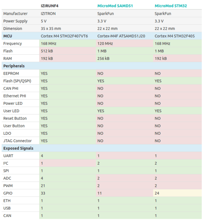
We noted Sparkfun MicroMod was a similar concept in the introduction, so IZITRON provided several comparisons of IZIRUN and MicroMod boards, including the table below for mid-range boards.
While IZIRUN boards will offer extra features and I/Os, at this point in time, Sparkfun MicroMod ecosystem is larger with multiple carrier boards and a choice of microcontrollers from Raspberry Pi RP2040 to Espressif Systems ESP32 WiSoC.
IZIRUN STM32 development boards are now available on Crowd Supply with a $6,600 funding target. A $30 pledge is asked for IZIRUNF0, $45 for IZIRUNF4, and $60 for IZIRUNF7. For reference, Sparkfun MicroMod processor boards sell for under $15, although with less features. The baseboard itself costs $60, but at least free international is included for all rewards. Backers should get their boards shipped by the end of October.

Jean-Luc started CNX Software in 2010 as a part-time endeavor, before quitting his job as a software engineering manager, and starting to write daily news, and reviews full time later in 2011.
Support CNX Software! Donate via cryptocurrencies, become a Patron on Patreon, or purchase goods on Amazon or Aliexpress




Cute concept and the m.2 socket seems ergonomically nice, but what’s the advantage of this vs something an arduino clone like a blue pill ? They seem identical, just plugging in with two pin rows.. this way seems like more of a pain to hand assemble and we’re talking 2-4 usd per chip board vs 30 usd
The table seems to list a bunch of external perpherals (that maybe you wouldn’t get on a lil arduino clone) – wouldn’t you want most of those on the baseboard and not the chipboard itself?
These are genuine questions from a noobie 🙂 I’m trying to set up a little logger with some input lines and an sd card slot on a baseboard for a blue pill (since I don’t know enough electronics to confidently layout a full board with an stm32 chip – this way seems more approachable)
I guess this is more designed to run an RTOS than arduino type software, in which case the additional on-board NAND and Ethernet + CAN connectivity (for the F4 and F7) are welcome.
These modules are probably more meant for people trying to squeeze a design based on STM32 discovery boards, but keep the baseboard design simple by handling the more complex parts of the layout.