Yesterday, I wrote about LilyGO TTGO ESP32-S2 WiFi IoT board, but one commenter mentioned it missed one of the key features of ESP32-S2 chip: a USB OTG port. While USB OTG is accessible through the header pins, it’s not the most convenient to use.
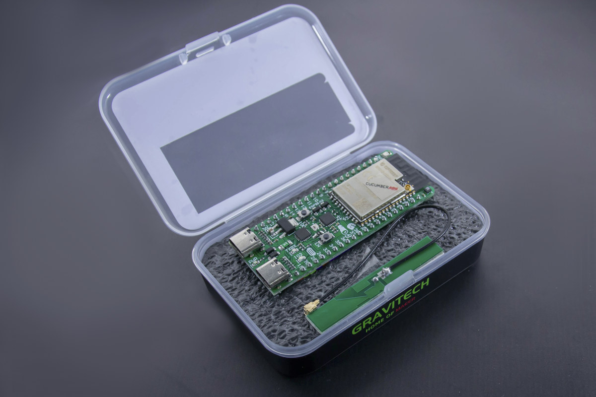
I also quickly mentioned Cucumber ESP32-S2 development board in that post, but I did not expand too much since I thought it should only ship within Thailand. But the board does include two USB Type-C ports, one for the usual USB UART connector, and the other for USB OTG, and I found out the board is available worldwide.

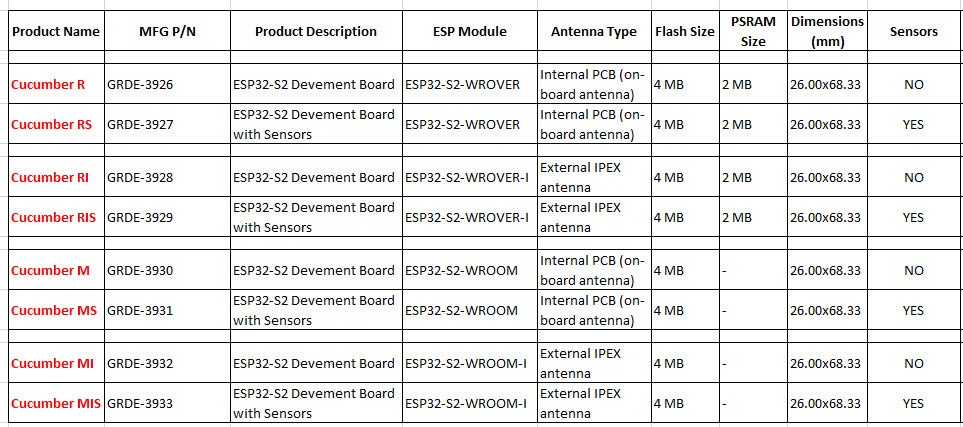
The board is available in multiple variants with or without sensors and PSRAM, and with external IPEX antenna or PCB antenna using ESP32-S2-WROVER(-I) or ESP32-S2-WROOM(-I) module.
Cucumber specifications:
- Wireless Module (one of the other):
- ESP32-S2-WROVER with ESP32-S2, 4MB flash, 2MB PSRAM, on-board PCB antenna
- ESP32-S2-WROVER-I with ESP32-S2, 4MB flash, 2MB PSRAM, IPEX / u.FL antenna
- ESP32-S2-WROOM with ESP32-S2, 4MB flash, on-board PCB antenna
- ESP32-S2-WROOM-I with ESP32-S2, 4MB flash, IPEX / u.FL antenna
- Connectivity – 2.4 GHz 802.11b/g/n WiFi 4 with ToF (Time of Flight) support
- USB
- 1x USB Type C port for power and programming via FTDI chip
- 1x USB OTG Type-C port
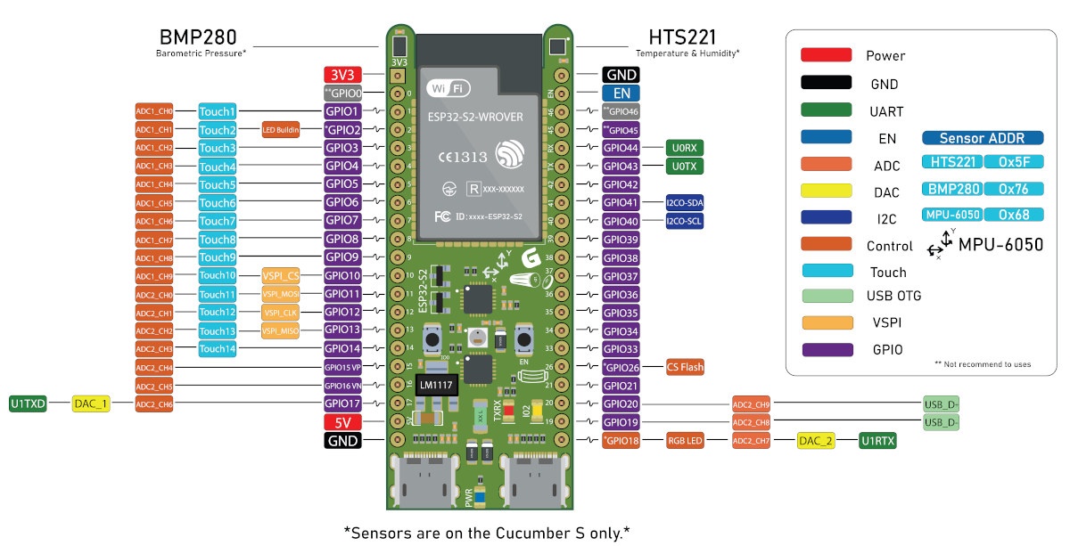
- Sensors (“S” versions only)
- HS221 Temperature & Humidity sensor
- MPU-6050 3-axis Accelerometer & 3-axis Gyroscope
- BMP280 Pressure sensor
- Expansion – 2x 21-pin header (color-coded) with GPIO, UART, SPI, I2C, ADC, DAC, Touch, USB OTG, 5V, 3.3V, and GND
- Misc – Boot and reset buttons; RGB LED; power, user (IO2) and UART LEDs
- Power Supply – 5V via USB-C port
- Dimensions – 68.33 x 26 mm

The naming convention is fairly easy to figure out with “R” being for WROVER module (PSRAM) and “M” for WROOM module. If “S” is present that means all three sensors are included and adding “I” means you’ll get an external IPEX antenna instead of an on-board PCB antenna.

The board can be programmed with ESP-IDF framework, and it’s also possible to use it with the recently announced ESP RainMaker providing easy access to sensor data and I/Os within an Android or iOS mobile app. bellmustachecat explains how to get started with ESP-IDF and sensors on Medium (Thai language, but screenshots in English). The company ported Arduino Core for ESP32 to the board with the code available on Github.
Cucumber development board is sold worldwide on Gravitech.us for $13.75 to $21.25 plus shipping. If you are based in Thailand, you should probably purchase it from GravitechThai instead.

Jean-Luc started CNX Software in 2010 as a part-time endeavor, before quitting his job as a software engineering manager, and starting to write daily news, and reviews full time later in 2011.
Support CNX Software! Donate via cryptocurrencies, become a Patron on Patreon, or purchase goods on Amazon or Aliexpress


While the board looks fairly complete (I didn’t know ESP32 supported OTG btw), I didn’t see any option to have it without the pins soldered, so it’ll remain a development board, while it could easily be used inside drones, robots or weather stations.
> without the pins soldered
Looking at the image, those low profile pins aren’t exceeding the height of the SoC itself.
The pins are not “low profile” on the under side.
I’m talking about the short ends. The long ends can be trimmed off with a wire cutter and if your product run is using so many units that you can’t afford the 2min per board of trimming, you’re going to be ordering a custom batch so they’re not worth considering in my view.
ESP32 does not support OTG but ESP32-S2 does.
Don’t know why you assume the pins need to be soldered. Various attachment options exist.
If you have a look at the site, you’ll see various combinations ({R,M}[i][S]) but all those I checked always have the pins on all photos and I couldn’t find a mention of an option not to have them soldered, so I don’t know where you saw the “various attachment options”.
Using the pins as provided, you could mount these boards via female headers on a mother board and/or use ribbon cables. Admittedly, it is a little surprising that the boards are only offered with the header pins already fitted (“soldered” in your parlance).
They’re also available on Mouser Electronics.
https://www.mouser.com/Search/Refine?Keyword=cucumber
I’ve been informed that some features like USB host mode and Time-of-Flight are not yet supported on ESP32-S2.
You can find an updated list of currently supported features at https://esp32.com/viewtopic.php?f=10&p=56361
Why would any engineer put sensors right next to the WIFI module? You will hardly find any place on the board offering more heat and RFI… Do they outsource their development to some apes?