USB to serial chips are often used as a debug interface either directly on the target board, or via a dedicated debug board. But some models have extra pins exposed, and one of those is WCH CH341, which also includes I2C & SPI interfaces and up to 8 GPIOs.
But software support for those extra pins is not currently built-in into the drivers found in Linux mainline, and you’d also have to find a board that breakout the relevant pins. It turns out there are few of things including “CH341A ALL IN 1 USB to SPI/I2C/IIC/UART/TTL/ISP serial adapter” board going for $10 shipped on Aliexpress, and which Zoobab successfully used to control 6 (out of 8) GPIOs over USB.
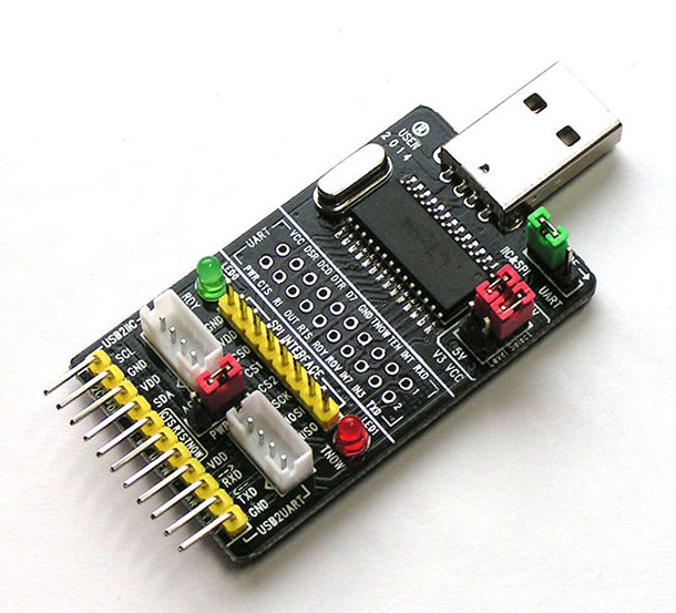
The board comes with a USB board to connect to your computer, several header for I2C, UART, SPI, some LEDs, and jumper to select I2C/SPI or UART mode and voltage (5V/3.3V).
The board is recognized differently whether you use I2C/SPI or UART mode in Linux:
- I2C-SPI mode
|
1 2 3 4 5 6 |
$ lsusb Bus 002 Device 003: ID 1a86:5512 QinHeng Electronics CH341 in EPP/MEM/I2C mode, EPP/I2C adapter $ dmesg [ 1739.299811] usb 2-1.2: new full-speed USB device number 3 using ehci-pci [ 1739.385559] usb 2-1.2: New USB device found, idVendor=1a86, idProduct=5512 [ 1739.385565] usb 2-1.2: New USB device strings: Mfr=0, Product=0, SerialNumber=0 |
- UART mode
|
1 2 3 4 5 6 7 8 |
$ lsusb Bus 002 Device 004: ID 1a86:5523 QinHeng Electronics CH341 in serial mode, usb to serial port converter $ dmesg [ 1982.227595] usb 2-1.2: new full-speed USB device number 5 using ehci-pci [ 1982.313544] usb 2-1.2: New USB device found, idVendor=1a86, idProduct=5523 [ 1982.313550] usb 2-1.2: New USB device strings: Mfr=0, Product=0, SerialNumber=0 [ 1982.314088] ch341 2-1.2:1.0: ch341-uart converter detected [ 1982.315989] usb 2-1.2: ch341-uart converter now attached to ttyUSB0 |
You’ll however need the out of tree i2c-ch341-usb driver to expose the 8 GPIOs and control them over USB/I2C. He set the direction to output for 6 of the pin in the source code (6-7 could not be set to output for whatever reason):
|
1 2 3 4 5 6 7 8 9 10 11 12 |
struct ch341_pin_config ch341_board_config[CH341_GPIO_NUM_PINS] = { // pin GPIO mode GPIO name hwirq { 15, CH341_PIN_MODE_OUT , "gpio0" , 0 }, // used as output { 16, CH341_PIN_MODE_OUT , "gpio1" , 0 }, // used as output { 17, CH341_PIN_MODE_OUT , "gpio2" , 0 }, // used as output { 18, CH341_PIN_MODE_OUT , "gpio3" , 0 }, // used as output { 19, CH341_PIN_MODE_OUT , "gpio4" , 1 }, // used as output with hardware IRQ { 20, CH341_PIN_MODE_OUT , "gpio5" , 0 }, // used as ouput { 21, CH341_PIN_MODE_IN , "gpio6" , 0 }, // used as input { 22, CH341_PIN_MODE_IN , "gpio7" , 0 } // used as input }; |
After after build the module, and load the module:
|
1 2 3 |
make sudo make install sudo modprobe i2c-ch341-usb |
gpio0 to gpio5 would should in /sys/class/gpio, which means you can control them with the usual sysfs commands:
|
1 2 |
echo 0 > /sys/class/gpio/gpio1/value echo 1 > /sys/class/gpio/gpio1/value |
He also benchmarked the pins with a shell script to turn on and off connected LED, and managed to do that at around 2.2KHz. It may be a little faster by changing the I2C bus speed (100 kHZ by default) and/or using C code instead. Alternatively, using spi-ch341-usb driver from the same developer (gschorcht) may speed things up a little bit despite the documented “slow SPI”.
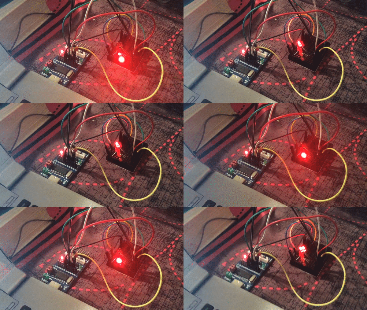
Another shell script with 6 LEDs connected to the board is demonstrated below.
Anyway that good news since that means you can add (extra) GPIOs to any Linux board with USB relatively easily and cheaply. But if you’re not quite willing to spending $10 on that option, there are cheaper options such as a CH341 USB programmer going for $2.30 + shipping on Electrodragon, or CJMCU-341 board sold for around $5 including shipping on Aliexpress or eBay.

Jean-Luc started CNX Software in 2010 as a part-time endeavor, before quitting his job as a software engineering manager, and starting to write daily news, and reviews full time later in 2011.
Support CNX Software! Donate via cryptocurrencies, become a Patron on Patreon, or purchase goods on Amazon or Aliexpress


Very nice, thanks
LOL, i used an FTDI chip for this years ago. It ran a Nixie tube clock with some shift registers. It was controlled by a WR703n with OpenWRT. I also made a LED version, but it wasn’t that cool and ended up in a drawer ( i think).
What’s the performance in I2C mode like?
Out of tree drivers suck badly. Is it going to be merged upstream?
It seems to me this would be a lot easier to control with the userspace I2C interface (if the kernel exposes this when detecting that board in I2C mode), or else just with libusb. This large out-of-tree kernel driver is really overkill.
After thinking about this a bit more, it occurs to me that using something like a Blue Pill board for this kind of functionality might make a lot more sense. You could put firmata on it or program it directly to perform whatever task you need.
Only 6 out of 8 GPIO’s work and the software end is incomplete. Some things never change 🙂
Is this device suitable to talk to i2c slaves from a Linux laptop? Do you have any other recommendation for this purpose?
hi cnx, do you suggest FT232H (yes H) to utilize spi ,uart etc ?
@hex
I don’t know, I’ve never used such serial chip to control GPIOs myself. So I’ll let other people who did answer.
@willmore
Yeah or just your run of the mill Arduino (clone) https://github.com/BLavery/virtual-GPIO
@willmore
yes I found a firmware for the stm32 that does GPIOs over USB, with a userspace tool on the host side to control them. Now they do not support the bluepill yet, but it is on my todolist: https://chromium.googlesource.com/chromiumos/platform/ec/+/master/chip/stm32/
@are
Maybe one day. I don’t know if the original author has the will/energy to make a pull request to the kernel. Plus let’s say the “mainline” status of such USB chip with some GPIOs drivers is pretty a disaster, not to mention the tendency of the GPIO maintainers stack to consider sysfs “legacy”. There were attempts in the past to merge sysfs gpio drivers for FTDI: failed (http://www.zoobab.com/ftdi-gpios-sysfs), same for PL2303 (the PL2303TB version has 12 GPIOs) (http://www.zoobab.com/pl2303hxd-gpio), not to mention Cypress (http://www.zoobab.com/pl2303hxd-gpio#toc6).
a Pi0 with his own OS (otg-mode, power supply via usb cable, no sd requiered) may be an option (5-9 $ + usb-cable+shipping) : https://www.raspberrypi.org/blog/gpio-expander/
See also this board with atmega8 with sysfs and 22 gpios:
https://github.com/amitesh-singh/usb-gpio-board
Not an off te shelf board though.
Excellent solution
@zoobab
I wonder if an AVR programmer based on Atmega8 could be reflashed to run it…
Or just bit-bang a 74HC194 4-bit bidirectional universal shift register from a user-land snippit.
6-7 could not be set to output for whatever reasonAt least the USB vendor protocol doesn’t allow writing to D7 because the sevent bit on the command frame is used to indicate data direction (write or read)
#define CH341_CMD_UIO_STM_IN 0x00 // UIO interface IN command (D0~D7)#define CH341_CMD_UIO_STM_OUT 0x80 // UIO interface OUT command (D0~D5)
#define CH341_CMD_UIO_STM_DIR 0x40 // UIO interface DIR command (D0~D5)
#define CH341_CMD_UIO_STM_END 0x20 // UIO interface END command
#define CH341_CMD_UIO_STM_US 0xc0 // UIO interface US command
Next step is to write a sysfs and a gpiochar driver for an stm32 bluepill board with the right firmware.
@zoobab
How about a firmata to native Linux driver shim?
@willmore
I am gonna play with the chromium-ec firmware, because there not much to do, just to try it out first, if you have the right stm32 supported board, some nucleo I have is supported.
Then I will look at firmata.