Earlier this year, I wrote about Electronut Labs’ Bluey development board powered by Nordic Semi nRF52832 development board with BLE, NFC, and a few sensors, and partially open source hardware with the KiCAD schematics and PCB layout available on Github.
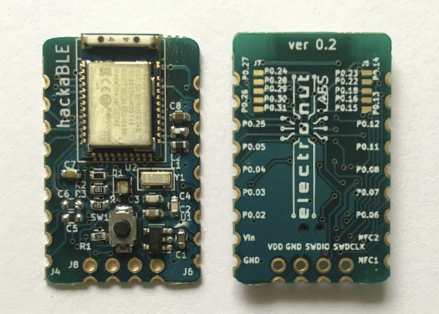
The company is now back with another open source hardware nRF52832 BLE board, namely hackaBLE, that’s much smaller (28x18mm), and with 2.54mm pitch castellated pin headers making suitable for use for breadboard, or as a module on a custom designed board.

hackaBLE board specifications:
- SoC – Nordic Semi nRF52832 ANT + BLE ARM Cortex-M4 @ 64 MHz processor with 512kB flash, 64kB RAM
- Connectivity – Bluetooth 4.2/5 LE and other proprietary 2.4 GHz wireless standards via chip antenna
- Expansion
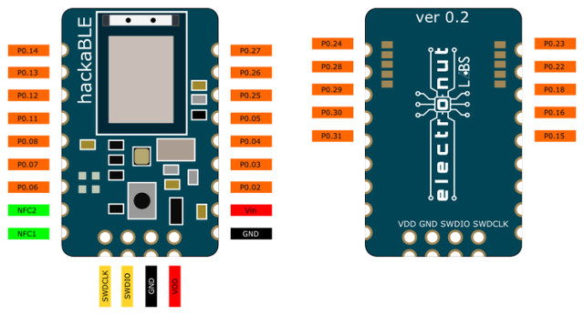
- 2x 9-pin castellated headers with GPIO, 5V, 3.3V, and GND
- 2x 5-pin solder pads for more I/Os
- Debugging – 4-pin SWD header
- Misc – RGB LED, and user button
- Power Supply – 5 V via VDD or Vin pin.
The company explains “hackaBLE use offers more value than just using the BLE module directly – since it incorporates the necessary passive components – including the ones for the buck converter for power saving – and adds an RGB LED and a button for convenience. It’s also much easier to solder than the bare modules.”. More details, including the KiCAD schematics and PCB layout can be found on Github, as well as the PCB footprint for the board for those who plan on making a custom board.

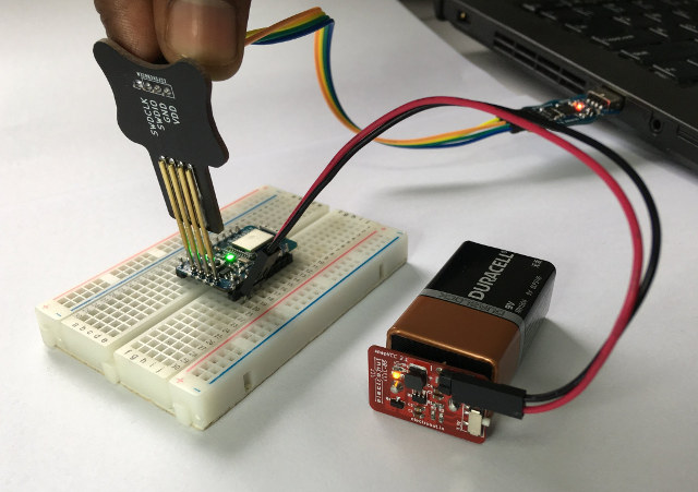
The company can also provide PogoProg board with 4 pogo pins to program the board through the SWD header, Bumpy SWD debugger, and snapVCC board outputting 5V/3.3V from a 9V battery.
hackaBLE can be purchased from Tindie for $20, and you could also get the $44 premium devkit with hackaBLE and the three boards mentioned and pictured above.

Jean-Luc started CNX Software in 2010 as a part-time endeavor, before quitting his job as a software engineering manager, and starting to write daily news, and reviews full time later in 2011.
Support CNX Software! Donate via cryptocurrencies, become a Patron on Patreon, or purchase goods on Amazon or Aliexpress


Here’s a picture of a breadboard friendly mounting:
https://plus.google.com/u/0/+DavidWillmore/posts/2XUApFqm72b
See how it only uses the inner row of pins–like an 0.3″ IC does? It elaves the whole rest of the breadboard for the user. Ideally, it would be shorter so that running wires over it wouldn’t be such a pain. Also, the pins need labeled in such a way that the can be more easily read by the user. For this Blue Pill example the bottom pins have their labels hidden which isn’t optimal.
Extra I/O goes off the ends of the boards.
@willmore
That’s an interesting design.
I understand you bended straight headers yourself. What if you had used 90 deg. headers?
@willmore
I’ve been thinking about doing something similar when experimenting with ESP12 modules, but haven’t found such long, already bent pin headers either. All those so-called “breadboard friendly” devices are not that friendly when you see how many holes are left once you plug them :-/
The best I could come up with using ESP12 was wasting a single hole per side : http://wtarreau.blogspot.fr/2017/08/what-esp8266-modules-should-look-like.html
For ESP12 there are also PCBs placing all pins in a single row, but that’s not optimal, and your mounting method imitating a DIL is better and more optimal in my opinion. And it even takes less vertical space because it doesn’t require the routing that normally takes space on a PCB.
@cnxsoft
I used a stock 90 degree for the shorter header. I tried and tried, but could not find a premade header anything like what I needed for the longer section. I need to reach out to Samtec or someone and see if they have something similar.
@willy
Yeah, my search for prebent ones failed miserably. There are a few companies that sell longer pre-bent ones, but they’re all in very specific lengths that won’t fit this purpose–they must be one-off parts for something pretty specific.
You bring up a good point. It might make more sense to design a board with this type of mounting in mind–you could put the pins all near the bottom in two rows like a 2xN 0.1″ connector. Then just solder one short 90 degree on one face and the other slightly taller (0.1″) 90 degree on the opposite side. The labels could be put on the top of the board as silk screen text, maybe? Labeling is what ends up making my method non-ideal.
I wonder if I did a board layout, if I could get some Chinese vendors to start making knockoffs and do the hard work of manufacturing for me? 😉 Leverage your strengths. 🙂
@willmore
I think it’s important to continue to experiment with such chips and breadboard-friendly designs. The NodeMCU, WeMOS D1 and friends are example of successes fixing a bad design (because quite frankly the ESP12 design is broken beyond imagination). The chip you used is even worse for mere mortals like us.
I too would be very happy to see some Chinese board makers decide to copy whatever idea comes from these experiments. I’d rather pay a few bucks for a device following my needs and some ideas I came up with than spending my time bending pins and soldering thin wires!