Broadlink MP1 is an inexpensive ($20) power strip with four international sockets that can be controlled over WiFi. Since I was interested in finding out how the power strip was designed internally, I asked GearBest whether they could send a sample for evaluation, which they did, and I got it today. So I’ll first check the device, and hardware design, before trying it with the Android app.
Broadlink MP1 Unboxing
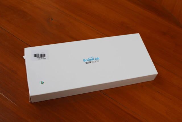
I don’t have much to say about the package, it’s just a bland white box with Broadlink logo.
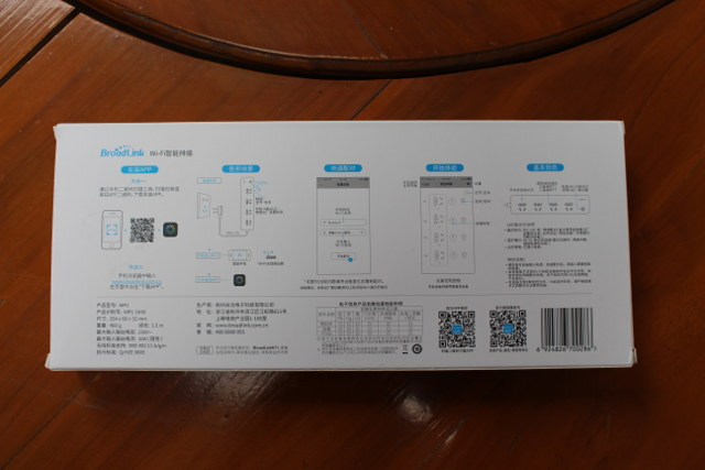
The bottom of the package is useful however, as it contains a sort of user guide in Chinese together with the specifications. I could not find any mentions of CE/FCC/CCC (for WiFi) or UL/TUV (safety) certifications on the package.
There’s no more information inside the box, except what looks like a warranty card in Chinese.
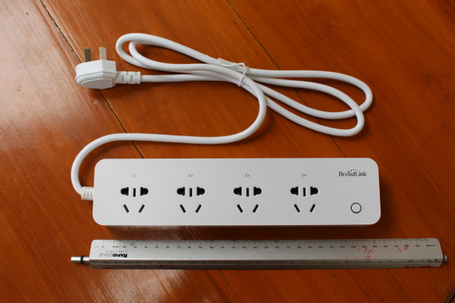
The power strip itself has four multi-standard sockets, a power button, and a 1.5 meter lead with a Australian 3-prong plug. Spacing between each socket is a good 5 cm as advertised.
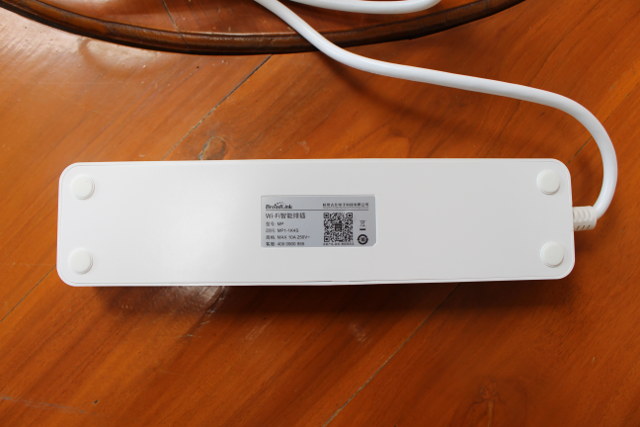
The bottom on the power strip includes some information including the model number (MP1-1K4S), maximum current and voltage (10A/250V), and a QR core linking to a QQ page redirecting to WeChat app in Google Play Store, so I did not try further…. The device is made by Hangzhou GuBei Electronics Technology.
Broadlink MP1 Teardown
We can open the device by removing the four rubber pad, and loosening 4 screws, as well as an extra screw placed right on the QR code.
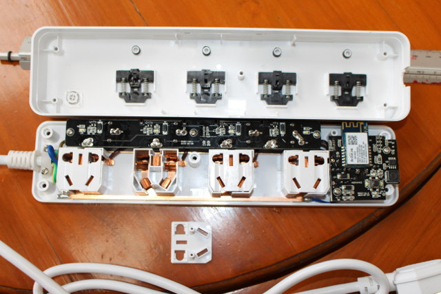
I’m not the best person to evaluate the design of this type of product, but I can see three wires including the ground are connected, the parts carrying the mains appear to be large enough, but I don’t see any type of fuses, which might be suitable in that sort of thing. You may want to check out the comment section, as hopefully more knowledgeable people may give their input. The long board is the really board, and the square board is the brain of the design with the WiFi module.
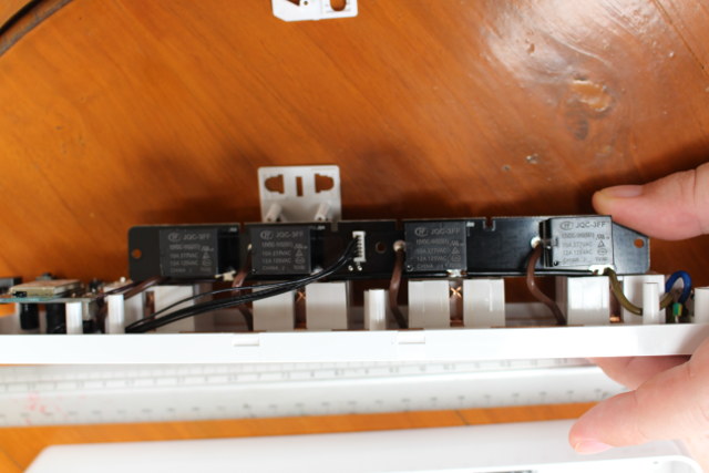
Four JQF-3FF 12V relays supporting 10A @ 277VAC / 12A @ 125VAC are used to control the sockets. A cable with 4 GPIOs (R1 to R4), GND, and 12V signals is connected between the relay board and WiFi board.
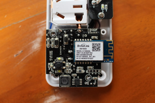
The board (PCCII-U1-2) includes a Broadlink WiFi module, the power button, two LEDs, and an unpopulated “GSRV” header to connect an ISP programmer. The small chip on the bottom of the pic is XLSemi XL1509 DC-DC converter.
I can’t find specific information about W1SBS03L WiFi module, except through its CMIIT ID, a product ID assigned by the China Ministry of Industry and Information Technology to identify wireless products in the Chinese market. The aforelinked website indicates the module operated in 2400-2483.5MHz frequency range, emits less than 20dBm (EIRP), occupies less than 40MHz bandwidth, and its emissions are inferior than -30 dBm. What I could not find it which chip that module is using.
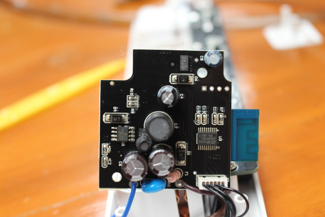
The bottom of the board has two more small ICs: STMicro STM8S003F3P6 8-bit MCU, and MP157 regulator.
Broadlink MP1 Power Strip Review
I’ve also tried the power strip. The first step is to scan the QR core on the package, to install the same e-Control app used on Broadlink SP2, or other Broadlink WiFi devices for home automation.
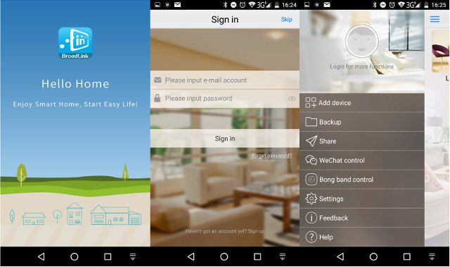
After the welcome screen, you’ll be asked to register or sign-in, but simply select Skip on the top right. If you want to control the plug over Internet, instead of just your local network, you may have to register however. You’d then have to tap on the three blue bars icon to bring the left menu, and select Add device.
At this stage I also connect the power strip, and the power button LEDs will start blinking regularly meaning the strip is ready for configuration.
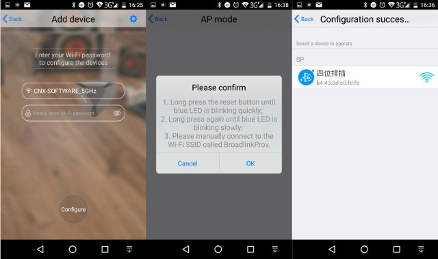
You’ll be presented with a first window asking you to enter your WiFi password, but when I tried to do this it failed each time. Instead tap on the top right Setup button and switch to AP mode. Click OK in the the second screen shown above, select your access point, enter your password, and you should be able to find the power strip pre-named with a name in Chinese (4-socket power strip).
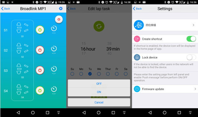
You’ll be able to turn on or off individual sockets, set timers to turn on or off specific a socket, control all sockets with a single button, or go to settings to change the power strip name, lock the device so that only your device can control the socket, or update the firmware. If you don’t have your smartphone with you, it’s also possible to turn on or off all sockets by pressing the power button on the unit.
I’ve scanned the power strip for both UDP and TCP port with nmap, which reports all TCP ports are closed, and all UDP ports are open|unfiltered.
I’d like to thank GearBest for sending Broadlink MP1 for review, and if you’re interested you could consider buying the device from them for $22.39 shipped. Banggood used to have a promo selling it for just under $20, but the price is now $22.79. You’ll also find Broadlink WiFi power strip on Aliexpress, but the prices are normally around $25 or greater.

Jean-Luc started CNX Software in 2010 as a part-time endeavor, before quitting his job as a software engineering manager, and starting to write daily news, and reviews full time later in 2011.
Support CNX Software! Donate via cryptocurrencies, become a Patron on Patreon, or purchase goods on Amazon or Aliexpress




Looks like a ESP8266 or RTL8710 running in AT command mode. That’s why they needed to add the STM8S003F3P6; they did not want to change the code in the wifi module. This is a decent design. MP157 was good choice for power supply. Only fault I see is that it could have been smaller/cheaper by directly mounting the prongs from the sockets into the PCB and the positioning the relays between each socket. As is – around $8 to produce this.
BTW – there has to be a port open somewhere on it. Don’t try and hook any test equipment up to this unit, it appears to be hot ground, you will destroy anything you attach to it. To program this unit it needs to not be plugged in, then isolated power is supplied over those four ISP connector points.
@Jon Smirl
I think I’ve read nmap results too fast:
All TCP ports are closed, but all UDP ports are open?
I repeated the test for UDP 1-65536, and it still says all ports are open. For TCP 1 to 65536 all ports are closed. I’d have to capture packets to find out which UDP port is used…
Is there bluetooth support on that chip ? (or other similar products)
@agumonkey
The module does not support Bluetooth. I’m not aware of any Bluetooth power strips, except for some hacked / DIY versions.
@cnxsoft
Thanks a ton
@Jon Smirl
It looks you are correct. The STM8 MCU is the one connected to the ISP header, and I assume it can be programmed using ST-LINK V2. The only thing is to find out which (AT) commands are used to control the WiFi module, and then we should be in full control…
wow interesting product. The price also makes sense. I can imagine a lot of applications since it is portable just like a regular power-strip.
Jon are you able to capture the packets between your phone power-strip. If it uses a simple TLV based app-protocol in UDP, then we can control it through scripts via our PC/laptops. I appreciate your nmap tests 🙂
Note that that this thing is using Chinese plugs/sockets, not Australian, they’re similar, but not the same. The ground pin faces down in Australia, on this one it faces up. Also the pins are a smidgen longer on Australian plugs. The live and neutral pins are also partially insulated on most Australian plugs.
On a side note, something like this, would from this year also require a rely on the neutral to be allowed to be sold in Australia. Go figure why, but it’s the latest confusing regulation there.
@agumonkey
There is/was the Silvershield Bluetooth (SIS-PM-BT), but apparently it only has/had drivers for Windows XP.
@TLS
They seem to be compatible: http://www.australianfrequentflyer.com.au/community/your-questions/mainland-china-power-plugs-adapters-40483.html
GearBest page says it’s an “Australian plug”, but they may be wrong of course. I just don’t know how to check it,
What does “face down” mean in this context? Or do you mean on the ground pin faces down on the wall socket?
@Kiran
I might setup an OpenWrt router to capture packets later on. That’s a low priority task, so hopefully somebody else will try it before I do.
@cnxsoft
Australian wall socket and plug http://2.bp.blogspot.com/-qI41Mb4vEIE/U9yx4XCxs4I/AAAAAAAAAh4/stpLpRe4EgI/s1600/plug.jpg
“Official” Chinese wall socket https://ae01.alicdn.com/kf/HTB1r0Z9KpXXXXbdXFXXq6xXFXXXP/free-shipping-3-Holes-16A-White-Panel-wall-Socket-Wall-Outlet-Power-Outlet.jpg
and plug http://www.tour-beijing.com/blog/wp-content/uploads/A-three-prong-Plug.jpg
They’re obviously inverted and the Chinese plugs don’t have the insulation, which is a legal requirement as far as I’m aware, much as with Euro plugs (which are only rated up to 2.5A).
However, most significantly, it seems like Australia has the live/neutral switched compared to most of the rest of the world.
https://en.wikipedia.org/wiki/AS/NZS_3112
I wonder how many homes there wil burnoff.
@Jeroen
This does not have UL approval, but nothing I see is screwing out “UL fail” to me. It even has the child guard covers over the outlets, not a lot of products have that.
Don’t poke around inside of this unless you know what “hot ground” means. It is very easy to kill yourself poking around inside a device like this. “hot ground” is not inherently unsafe and it is used in a lot products. It is just something that an inexperienced home hacker should not be playing with. There are exposed mains voltages all over these PCBs.
@Jon Smirl
It seems like there is no surge/transient protection and no over current protection and who knows about flammability ratings.
See F1 and RV1 on the power supply board next to the blue wire (last photo).
Look at page 17 in the MP157 datasheet
https://www.monolithicpower.com/DesktopModules/DocumentManage/API/Document/GetDocument?id=11
The board can pass 2kV surge test by using the
circuit below.
1) Change the fuse resistor F1 (10ohm/1W) to
SS-5-2A
2) Add a MOV RV1 (TVR14431)
“Australia’s plug/socket system is codified as standard AS 3112. Although there are slight differences (the pins of Chinese plugs are 1 mm longer and the sockets are installed with the earth contact facing upwards), the Australian plug mates with the socket used in the People’s Republic of China (mainland China).”
“The reason as to why the dimensions of the Australian type I are very similar to those of (American) type A is because the Australasian standard is actually an obsolete type of American plug. It was patented in 1916 by Harvey Hubbell II, the same electrical engineer who had invented the type A plug. Hubbell’s three-blade design never proved popular in the U.S. because of its incompatibility with the existing type A plug, but it was favoured in Australia over the British type D system, because it was easier for local manufacturers to make plugs with flat pins rather than round ones. In the 1930s, the predominant Australian electrical accessory manufacturers, along with the State Electricity Commission of Victoria, decided to standardize on Hubbell’s design.”
So, it seems the Chinese sockets are essentially 180-degree rotated Australian sockets, or are they upside-down Australian sockets (line & neutral swapped)?
More here:
http://www.worldstandards.eu/electricity/plugs-and-sockets/i/
@cnxsoft
I would love to know those AT commands… I have managed to bork a Haufansmart socket, the internal layout is very similar including the STI chip
Shortly before I wiped it out I saw an AT command on the serial bus.
I am going to bet that the firmware is the same in a lot of these chinese esp8266 based devices… I have managed to flash ESPEasy onto the ESP8266, I can see the STI chip on the serial, just need to re-create the commands, or alternately replace the STi chip with an avr based device that I can control…
@cnxsoft
Have you tested or do you know if there is a way to control it by eg. linux?
Regards,
eric
@Eric
Broadlink can provide an SDK/API if you plan to purchase in quantities.
Otherwise you’d have to flash your own firmware to the STM8 MCU and/or WiFi chip.
how it saves settings of switches if the main power off (like load shedding)
Hi, I got this Broadlink MP1, but even after numerous tries, I have failed to connect to the device via the App. Please suggest some solutions
Thank You
@Muhammad IRFAN
There must be an EEPROM or flash to save settings.
@Rohit Mandal
Does the power strip power LED blinks when you try to connect to it? If not, you may have to press the power button several seconds to enter “pairing” mode.
It used BiTrend wifi module. Datasheet is here https://fccid.io/document.php?id=2672275
@tsonha
Thanks. So that’s a Mediatek MT7681 module.
Got a couple of these, and due to the guard covers over the outlets, you cannot plugin a 2 pin AU plug, has to have the ground pin.
Hi
May I know, if I use this behind the firewall, what port I should open? (TCP or UPD)?
million thanks
K
Hi
I’ve been trying to get a refund on my purchase from Banggood. I’ve got version MP1-1K4S with firmware v10028 as the latest.
I have not been able to set this up on my network as it does not support extended characters on its wifi password like @. I’ve also found out on the web that it does not like wifi passwords that are too long though routers would support it.
Anyone know of a firmware update or hack to sort this out? I don’t want to reduce the complexity of my wifi network just to get this to run when everything else on my network is ok. BTW app reports the firmware as the latest.
If you router supports it, maybe setup an extra SSID and only allow the MAC of Broadlink MP1 to connect to it.