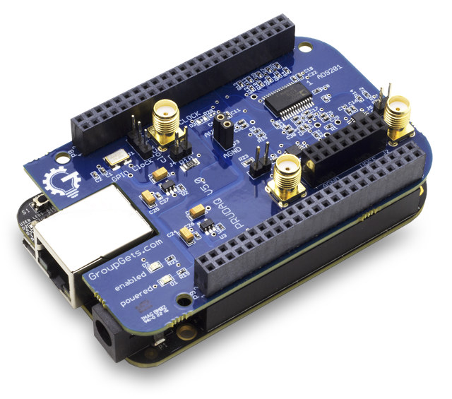
Engineers at Google Research wanted to measure the strength of a carrier signals without having to use a bulky oscilloscope or DAQ (Data Acquisition) system, so they looked into several makers boards to achieve this task, eventually decided to go with BeagleBone Black / Green, and created their own PRUDAQ cape capable of sampling 40 million samples per second, and open source it all.
- Dual-channel simultaneously-sampled 10-bit ADC (Analog Devices AD9201)
- Up to 20MSPS per channel (40MSPS total) theoretical
- 0-2V input voltage range (DC coupled)
- 4:1 analog switches in front of each channel provide a total of 8 single-ended analog inputs. (See here for differential input)
- SMA jacks for direct access to the 2 ADC channels
- Flexible clock options:
- External input via SMA jack
- Internal on-board 10MHz oscillator
- Programmable clock from BeagleBone GPIO pins
- Powered via BeagleBone headers – no external power needed
- Fully exposed BeagleBone headers on top to connect/stack more electronics or another cape
- Dimensions – 87mm x 56mm (+/- 1mm)
- Weight – 29 grams
The complete software and hardware documentation can be found on the Wiki and source code and design files in Github. The software is based on BeagleLogic logic analyzer, and you can retrieve and analyze the data on your computer using the command line with a typical output looking like:
|
1 2 3 4 5 6 7 8 9 10 11 12 13 14 15 16 17 |
$ sudo ./prudaq_capture -i 0 -q 4 -f 2000 pru0.bin pru1.bin | hexdump -d -v | head 2097152B of shared DDR available. Physical (PRU-side) address:91800000 Virtual (linux-side) address: 0xb6b9a000 Actual GPIO clock speed is 2000.00Hz 0000000 00000 00000 00001 00513 00001 00513 00001 00513 0000010 00001 00513 00001 00513 00001 00513 00001 00513 0000020 00001 00513 00001 00513 00001 00513 00001 00513 0000030 00001 00513 00001 00513 00001 00513 00001 00513 0000040 00001 00513 00001 00513 00001 00513 00001 00514 0000050 00001 00513 00001 00513 00001 00513 00001 00513 0000060 00001 00513 00001 00513 00001 00513 00001 00513 0000070 00001 00513 00001 00513 00001 00513 00001 00513 0000080 00001 00513 00001 00513 00001 00513 00001 00513 0000090 00001 00513 00001 00513 00001 00513 00001 00513 5256 bytes / second. 5256B written, 5256B read. |
The Beaglebone Black already has an ADC input, but PRUDAQ allows for much faster sampling, suitable to capture radio waves for example. Bear in mind that it’s not really suitable to be used as an oscilloscope due to limitations such as 0 to 2V range, and others. Any specific questions about PRUDAQ project can be asked on PRUDAQ users Google Group.
While the add-on board has been designed by Google Research engineers, it is not a Google product, and it’s made by GetLab, and currently sold on GroupSets for $79 for the cape only, or $159 as a bundle with a BeagleBone Black, PRUDAQ cape, an 8GB micro SD card pre-loaded with BeagleLogic image, one 64GB USB 3.0 Thumb Drive, one BNC-M to SMA-M RG-58 Cable, a USB mini cable, and 3 jumpers.

Jean-Luc started CNX Software in 2010 as a part-time endeavor, before quitting his job as a software engineering manager, and starting to write daily news, and reviews full time later in 2011.
Support CNX Software! Donate via cryptocurrencies, become a Patron on Patreon, or purchase goods on Amazon or Aliexpress


The Raspberry Pi is so popular, that it’s nice to see projects using the BeagleBone Black!
But, regarding alternative to bulky oscilloscopes, what’s wrong with the Red Pitaya or Digilent’s Analog Discovery 2? Both of which are about the same in size as the BBB, but have more bandwidth, high sampling, higher adc resolution than the PRUDAQ.
What kind of “carrier” are they trying to “measure” with a relatively slow 40 Msps ADC? Remember, even a cheap digital oscilloscope rate at 100 MHz (1-channel only) has a 1 Gsps (yes that’s G for Giga, not M for Mega) 8-bit interleaved ADC, and that is pushing it. So going by the same specifications, this 40 Msps ADC cape would do direct sampling to only around 4 MHz, maybe 8 MHz if you add some hardware filtering. (By the way, it looks like there’s little or nothing in the way of a front end on their board – not good.)
Why don’t they use a dirt cheap RTL-SDR dongle instead (you can do a direct sampling mod for lower frequencies)? If an RTL-SDR won’t cut it, there are a bunch of fairly inexpensive much improved SDR boards out there these days, and plenty of free software options too. Heck, even a cheap direct quadrature downconverter and a PC sound card would make a great carrier measurement tool depending on frequency and whether there is any modulation (bandwidth).
And why are these Google “Engineers” playing around with “Maker” level tools in the first place!? Google pays them tons of money every single day they waste fooling around like this. Google should buy them (or at-least rent them) some REAL test equipment. Even if they are doing hardware development, the are going to need real test equipment anyway!