The popularity of Raspberry Pico board powered by RP2040 microcontroller has made every reader wanting to know more about the board and chip. So today we will be talking about RP2040’s Programmable IOs, a feature that makes it different from most other microcontroller boards.
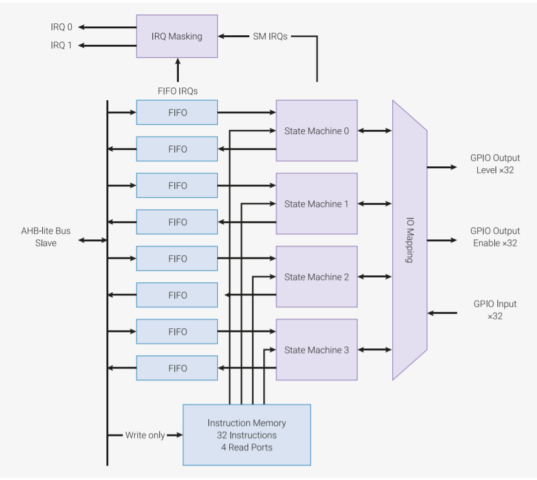
The two PIO blocks or let’s call it the hardware interfaces in the RP2040 have four state machines each. These two PIO blocks can simultaneously execute programs to manipulate GPIOs and transfer raw data. Now, what do these state machines do? Well, the PIO state machines execute the programs fetched from various sources. Sometimes the programs are taken from the PIO library (UART, SPI, or I2C) or user software.

Why Programmable I/O?
All the boards usually come with hardware support for digital communications protocols such as I2C, SPI, and UART. However, if you plan to use more of these interfaces than what is available on the board, you can use the programmable IOs provided in RP2040 microcontroller.
Well, this has more capabilities than one can think of. Let’s say you want to output a DPI video or “communicate with a serial device found on AliExpress” is now possible with Programmable I/O. As the name says, ‘Programmable’ IO makes it clear that it can be programmed directly to support several interfaces including SD card interface, VGA output, and higher speed data transfer. Hang on! We have the most exciting part of the article coming up – ‘How to program these programmable I/Os to make your job easy’.
How do I get started with the RP2040 PIO programming?
The Pico SDK (Software Development Kit) provides the headers, libraries and build system necessary to write programs for RP2040-based devices such as Raspberry Pi Pico in C, C++ or Arm assembly language
If you plan to use Python to code, you only require a suitable editor (let’s say Thonny) and MicroPython installed on the development board. But in the case of C/C++, you require CMake file that tells the Pico SDK how to turn the C file into a binary application for an RP2040-based microcontroller board, as explained in our recent MicroPython and C tutorial for Raspberry Pi Pico.
The PIO Assembler parses a PIO source file and outputs the assembled version ready for inclusion in an RP2040 application. This includes the C and C++ applications built against the Pico SDK, and Python programs running on the RP2040 MicroPython port.
To get started with programming the state machine for your PIO application, there are three components for C/C++ based program.
- A PIO program
- C-language based software to run the show
- A CMake file describing how these two are combined into a program image to load onto an RP2040-based development board.
PIO Assembly Instructions
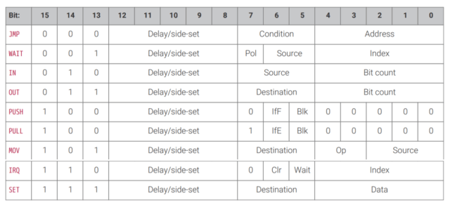
Now, when it comes to programming these IO interfaces, there are nine assembly instructions “JMP, WAIT, IN, OUT, PUSH, PULL, MOV, IRQ, and SET”. Although most people may be interested in programming the PIO interfaces with C/C++ or Python language, let us look into some of the assembly language instructions used for the IO interfaces.
- JMP: This ‘jump’ instruction can be a conditional or a non-conditional statement. In this, it transfers the flow of execution by changing the instruction pointer register. In simple words, with ‘jmp’ statement the flow of execution goes to another part of the code.
- WAIT: This instruction stalls the execution of the code. Each instruction takes one cycle unless it is stalled (using the WAIT instructions).
- OUT: This instruction shifts data from the output shift register to other destinations, 1…32 bits at a time.
- PULL: This instruction pops 32-bit words from TX FIFO into the output shift register.
- IN: This instruction shift 1…32 bits at a time into the register.
- PUSH: This instruction to write the ISR content to the RX FIFO.

More information about the assembly language instructions is available in the RP2040 datasheet.
RP2040 PIO programming example in C/C++ and MicroPython
To make it easier, we will look into the program of hello_world that blinks the onboard LED using the Programmable IOs and TX FIFO’s 32-bit data (PULL instructions).
The program in C/C++ looks something like this:
|
1 2 3 4 5 6 7 8 9 10 11 12 13 14 15 16 17 18 19 20 21 22 23 24 25 26 27 28 29 30 31 32 |
#include "pico/stdlib.h" #include "hardware/pio.h" // Our assembled program: #include "hello.pio.h" int main() { // Choose which PIO instance to use (there are two instances) PIO pio = pio0; // Our assembled program needs to be loaded into this PIO's instruction // memory. This SDK function will find a location (offset) in the // instruction memory where there is enough space for our program. We need // to remember this location! uint offset = pio_add_program(pio, &hello_program); // Find a free state machine on our chosen PIO (erroring if there are // none). Configure it to run our program, and start it, using the // helper function we included in our .pio file. uint sm = pio_claim_unused_sm(pio, true); hello_program_init(pio, sm, offset, PICO_DEFAULT_LED_PIN); // The state machine is now running. Any value we push to its TX FIFO will // appear on the LED pin. while (true) { // Blink pio_sm_put_blocking(pio, sm, 1); sleep_ms(500); // Blonk pio_sm_put_blocking(pio, sm, 0); sleep_ms(500); } } |
The above C/C++ code blinks the LED with one complete cycle of 1 second. LED is programmed in such a way that it will be on for 500 ms followed by off for 500 ms. But, before state machines can run the program, we need to load the program into this instruction memory. “The function pio_add_program() finds free space for our program in a given PIO’s instruction memory, and loads it.” With this, we configure the state machine to output its data to the onboard LED.
The assembly code for .pio file shown below has all the C helper functions to set C/C++ code.
|
1 2 3 4 5 6 7 8 9 10 11 12 13 14 15 16 17 18 19 20 21 22 23 24 25 |
.program hello loop: pull out pins, 1 jmp loop % c-sdk { static inline void hello_program_init(PIO pio, uint sm, uint offset, uint pin) { pio_sm_config c = hello_program_get_default_config(offset); // Map the state machine's OUT pin group to one pin, namely the `pin` // parameter to this function. sm_config_set_out_pins(&c, pin, 1); // Set this pin's GPIO function (connect PIO to the pad) pio_gpio_init(pio, pin); // Set the pin direction to output at the PIO pio_sm_set_consecutive_pindirs(pio, sm, pin, 1, true); // Load our configuration, and jump to the start of the program pio_sm_init(pio, sm, offset, &c); // Set the state machine running pio_sm_set_enabled(pio, sm, true); } %} |
Apart from these, you also require CMake file that describes how .pio and .c files are built into a binary suitable for loading onto your Raspberry Pi Pico development board.
There’s no equivalent sample written with MicroPython, but we can see a simpler PIO MicroPython code used to blink the onboard LED:
|
1 2 3 4 5 6 7 8 9 10 11 12 13 14 15 16 17 18 19 20 21 22 23 24 25 26 27 28 |
import time from rp2 import PIO, asm_pio from machine import Pin # Define the blink program. It has one GPIO to bind to on the set instruction, which is an output pin. # Use lots of delays to make the blinking visible by eye. @asm_pio(set_init=rp2.PIO.OUT_LOW) def blink(): wrap_target() set(pins, 1) [31] nop() [31] nop() [31] nop() [31] nop() [31] set(pins, 0) [31] nop() [31] nop() [31] nop() [31] nop() [31] wrap() # Instantiate a state machine with the blink program, at 1000Hz, with set bound to Pin(25) (LED on the rp2 board) sm = rp2.StateMachine(0, blink, freq=1000, set_base=Pin(25)) # Run the state machine for 3 seconds. The LED should blink. sm.active(1) time.sleep(3) sm.active(0) |
There’s no separate .pio file in this case, and both MicroPython and assembly code are placed into the .py file.
Note that even though PIO can be programmed with MicroPython, the Python SDK documentation says it’s currently unstable/work-in-progress, so C/C++ is recommended.
There can be many modifications to the code by adding the color you want to display with the help of the hex format in RGB. However, there are many real-life examples like PWM, UART or even interfacing NeoPixels. For those interested, you can find many PIO programming examples in the GitHub repositories for C and MicroPython samples.
Conclusion
RP2040 Programmable IOs have the capability to simultaneously execute programs to support interfaces like VGA output and higher speed data transfer. You can check Chapter 3 in the SDK documentation for C/C++ and Python to find out more about RP2040 Programmable IOs.

Abhishek Jadhav is an engineering student, RISC-V Ambassador, freelance tech writer, and leader of the Open Hardware Developer Community.
Support CNX Software! Donate via cryptocurrencies, become a Patron on Patreon, or purchase goods on Amazon or Aliexpress


