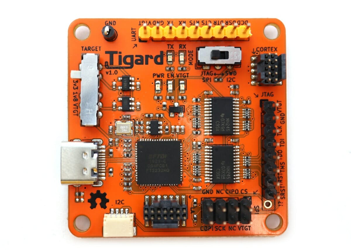
There is plenty of cheap 5V or 3.3V USB to TTL debug boards used to access the serial console and/or program boards, but FTDI FT2232H based Tigard open-source hardware board does much more than that as it supports multiple protocols, multiple voltages for hardware hacking & debugging.
The developer explains Tigard can be used as a drop-in replacement for dozens of other hardware tools based on FTDI chips and includes native support OpenOCD, FlashROM, and more.
Tigard board specifications:
- Main chip – FTDI FT2232HQ dual high-speed USB to multi-purpose UART/FIFO IC
- Primary port dedicated to UART including access to all flow control signals
- Secondary port shared among dedicated headers for SWD, JTAG, SPI, and I²C
- USB – USB 2.0 Type-C (480 Mbps) port
- I/Os
- 9-pin UART header
- Qwiic I2C connector
- 8-pin SPI & I2C header
- 8-pin JTAG header
- 10-pin Cortex debug header
- 14-pin logic analyzer (LA) header to observe device-level signals
- Directional level-shifters for 1.8 to 5.5 V operation
- Misc
- Switch to choose between on-board 1.8 V, 3.3 V, 5.0 V, and off-board vTarget supplies
- Switch to choose between SPI/JTAG and I²C/SWD modes
- Indicator lights to aid debugging
There’s no real need for Tigard-specific tools, and the board will work with standard tools and libraries including USB serial drivers, OpenOCD and UrJTAG for JTAG, Flashrom, PyFtdi/PySpiFlash, LibMPSSE, and other tools for the SPI interface, as well as LibMPSSE and PyFtdi/PyI2CFlash for the I2C interfaces.
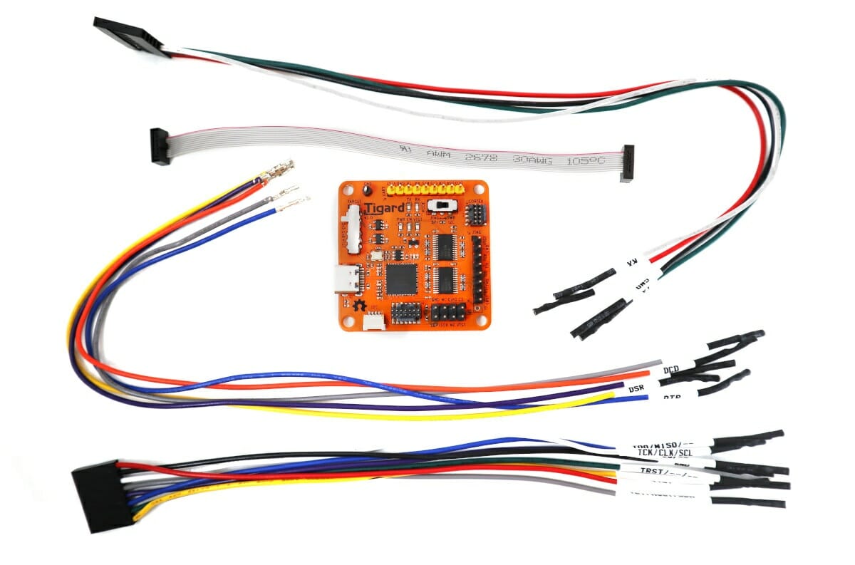
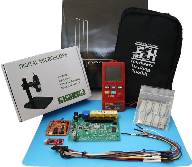
The board will ship with all necessary cables (SPI, JTAG, Cortex, serial) with each wire clearly marked. There are also two kits with the first one including Bitmagic logic analyzer board for live debugging of serial protocols using Sigrok / PulseView, and the second “Applied Physical Attacks Online Kit” further adding clips and connectors, a simple multimeter, an organizer pouch, a USB microscope, and a target system (unnamed Linux-based Wi-Fi router) as well as online access to over three days of lectures, labs, and support.
You’ll find the KiCAD hardware design files and some documentation on Github. Tigard has already raised over $20,000 on Crowd Supply with rewards starting at $39 for the board and wires, and going up to $1,337 for the complete kit shown above. Shipping is free to the US, and $10 to $20 to the rest of the world. Deliveries are scheduled to start in the second part of February 2021.
Jean-Luc started CNX Software in 2010 as a part-time endeavor, before quitting his job as a software engineering manager, and starting to write daily news, and reviews full time later in 2011.
Support CNX Software! Donate via cryptocurrencies, become a Patron on Patreon, or purchase goods on Amazon or Aliexpress
Great idea, I like that !
This kind of tool need a great community to have a great support .
Such tools are really needed. Spending hours flashing via a buspirate board, soldering on FTDI-like UARTs to access RTS instead of CTS when flashing ESP8266, replacing too weak 3.3V LDOs with AM1117 ones on UARTs to avoid a brown-out when connecting to 3V devices etc is a real pain. I recently bought an FTDI232H board for a few bucks that I ought to have bought earlier. This will give me fast SPI via MPSSE, plenty of auxiliary signals for the UART to handle automatic reset/flashing of ESP8266, a stronger 3V output. A device like above would additionally improve the voltage… Read more »
If this ever becomes available it should be interesting: https://github.com/GlasgowEmbedded/glasgow
Definitely filling a market void but $1337 for complete kit is admittedly steep for many 1 chicken tech schools. Technical ability for the masses is still some way off.
The $1337 option is more than just the hardware, it includes an entire online training course based on the Tigard and Bitmagic, including a target router, usb microscope, etc, by someone who has written the book on hardware hacking.
Toolkit with Tigard, Bitmagic, and more – everything you need for the self-paced “Applied Physical Attacks on Embedded and IoT Systems” online course which covers the basics of hardware hacking on embedded systems. Includes access to all online lectures, labs, and supporting materials.
This seems really handy if it works smoothly – though it’s hard to imagine the software side will match to something like a RPi (hope I’m wrong!) Probably a naiive question, but since this comes with a “14-pin logic analyzer (LA) header to observe device-level signals” – why is it being paired with a separate “Bitmagic logic analyzer board”? Could you use the LA header to have it analize itself? Or is this for a higher sampling rate? And would this function with Sigrok on it’s own as a basic logic analyzer? It’s be nice to have something basic that… Read more »
The idea is that you can plug on a separate logic analyser to debug the signals being emitted or seen by the FTDI chip – the header is just a convenient breakout point to tap each line.
I think the built in LA is going to be pretty useless and it’s basically a gimmick.
Imagine if they did this board but they also included a super cheap Linux capable SoC like that RISC-V thing or the V3S and you could just connect to a web server running on it and get access to uart, flashing etc via a nice flashy JS interface instead of having to deal with annoyances like flashrom[0] and friends.
0 – why can’t you just write data to an offset.. why do I need to create a dummy image with dd to update a single area. GAAHHHH!
And why do you have to create a fake image full of 0xff to avoid erasing a fresh new device!