I’ve just received the ODroid-X development board based on Samsung Exynos 4412 quad-core processor together with lots of accessories:
|
|
Since there is quite a lot of things to cover, today I’ll just show some unboxing pictures, how to connect all those modules to the board and run Android pre-loaded in the eMMC module, and I’ll do a more detailed review with Android and Ubuntu in another post.
I received the kit in a large box sent via EMS.
Here’s a picture with the board and all accessories present in the Box.

From top left to bottom right: 10.1″ LCD Modules, ODroid-X development board, HDMI to mini HDMI cable, micro USB to USB cable (for debugging), 5V/2A power supply for the board, 9V/1.5A power supply for the LCD module, WiFi dongle, Bluetooth dongle, 5MP camera module, 16GB eMMC module, USB to TTL board and LCD board. You’ll notice their is no documentation or CD included, that’s because everything you need is available on Odroid-X/Q project Wiki.
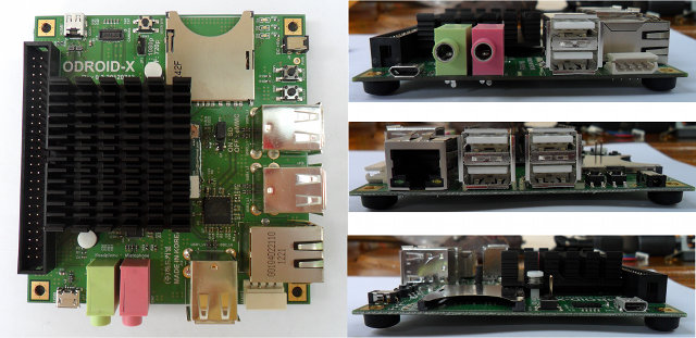
Let’s have a closer look at the board itself with a top view and 3 side views where you can see the different connectors, jumpers and buttons.
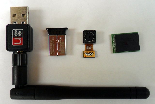
Here’s also a close up of the small Wi-Fi, Bluetooth, Camera and eMMC modules.
Now let’s connect all those together, and add a USB keyboard and a USB mouse.
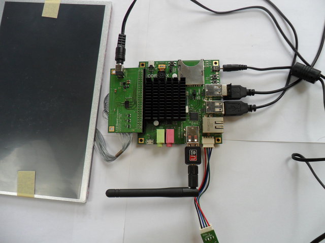
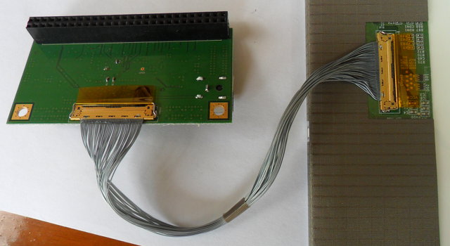
The eMMC is clipped under the board and obviously not seen on this picture. I’ve also added a picture showing how the LCD Module is connected to the LCD board. Once this is done simply connect the LCD board to the expansion header of the ODroid-X.
The first time I connect the debug board to my Windows XP netbook, the device was recognized automatically and CP2104 USB to UART driver installed properly, but suddenly it was not recognized anymore. I eventually fixed this issue by installing CP210x USB to UART Bridge VCP Drivers available on Silicon Labs website.
I’ve read somewhere that the eMMC comes pre-loaded with Android ICS, so let’s turn the power on! One LED lights (yes!), then nothing (damn!). After a few seconds of panic (sort of), I find out there is a jumper with the markings “ON: SD, OFF: eMMC”. Let’s remove the jumper then. Still nothing :|. Finally I realize there is a power button, something I haven’t seen for a while on the several boards I have. Let’s press that button. The debug output shows up in Putty, 4 Tux appear on the LCD (good 4 cores are detected), then the Android boot screen and finally:
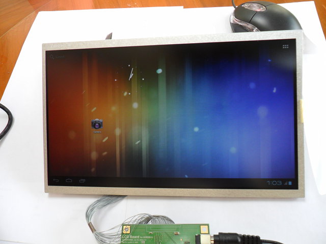
The boot took 25 seconds, the mouse, keyboard and Wi-Fi are working. That’s about it for today. I’ll give a more detailed review about Android, try all different peripherals and how I (hopefully) ran Ubuntu from a SD in another post.
The full kit described above costs 366 USD in total including shipping, for what looks like a pretty decent ARM (notebook) reference design. The 10.1″ LCD module is sold out, but there is a slightly more expensive 14″ display available. All modules are pretty standard, so you may not need to buy all accessories, and just buy the board for 129 USD + 40 USD shipping, although I’d recommend the 16GB eMMC module (the performance should be better than SD card) and possibly the debug board, if you don’t have one already.
You can find more information on ODroid-X page, get support in the forums, and get tips and How-tos by reading Hardkernel blog.

Jean-Luc started CNX Software in 2010 as a part-time endeavor, before quitting his job as a software engineering manager, and starting to write daily news, and reviews full time later in 2011.
Support CNX Software! Donate via cryptocurrencies, become a Patron on Patreon, or purchase goods on Amazon or Aliexpress


