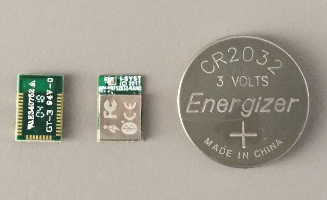
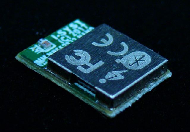
If you have a project requiring a programmable Bluetooth 4.x/5 module that’s as small as possible, Canada based I-Syst may have what you need with their IMM-NRF52832-NANO module measuring just 10 x 7 x 1.6 mm.
The module is based on Nordic Semi nRF52832 Arm Cortex-M4F SoC with Bluetooth 5 LE (no long range support) and ANT+ connectivity, and exposes up to 30 I/Os for your project.
- SoC – Nordic Semi nRF52832 32 bits Arm Cortex-M4F @ 64MHz with 512KB Flash, 64KB SRAM, 2.4GHz multi-protocol transceiver
- Connectivity – Bluetooth 5 LE, ANT+, Type 2 NFC -A Tag with wakeup on field
- Up to 30x I/Os:
- 3x SPI Master/Slave
- 2x 2-wire Master (I2C compatible)
- UART (CTS/RTS)
- 3x 4 channel PWM
- 8x configurable 12 bits, 200 ksps ADC
- Digital microphone interface
- Quadrature decoder input
- Sensors – Temperature sensor
- Security – AES HW encryption
- Misc – 32MHz & 32.768KHz crystals, low power comparator
- Power Supply – 1.8V to 3.6V DC input; DC/DC power mode inductors
- Dimension – 10 x 7 x 1.6 mm
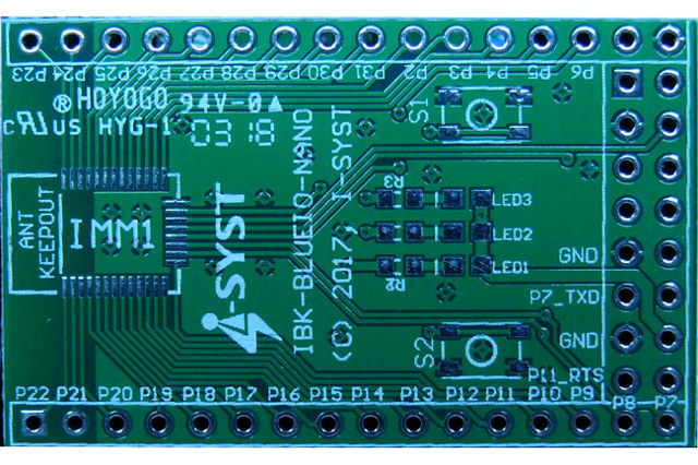
The module can be used without extra components and “the only space required on your PCB is the module size itself”, which makes it ideal for wearable and space-constrained applications. A getting started guide, source code samples, including iOS & Android apps can be found on the developer’s blog. A breakout board – pictured below – can also be provided to speed up development or for evaluation.
 IMM-NRF52832-NANO miniature module is sold for $18 on Tindie plus shipping, but you may also consider spending $3 extra for the DIP32 breakout board. More documentation can also be found on the Tindie link.

Jean-Luc started CNX Software in 2010 as a part-time endeavor, before quitting his job as a software engineering manager, and starting to write daily news, and reviews full time later in 2011.
Support CNX Software! Donate via cryptocurrencies, become a Patron on Patreon, or purchase goods on Amazon or Aliexpress


