Most schematics capture and PCB layout software run on Windows and are closed source. But if your favorite OS is Linux, there are a few open source software including Kicad and gEDA. There is also Cadsoft Eagle which can be installed in Linux with a free license for hobbyists and educational purposes, but is not open source.
Today, I’ll focus on Kicad. I don’t really capture schematics, let alone layout PCBs, but I sometimes need to use this type of software to locate pins/components on the schematics and PCB and check some parts of the schematics that can affect software. So I will mainly give an overview of Kicad and write my experience trying to import another project (Beagleboard XM) to Kicad. If you want to learn how to get started with your own project with Kicad, you might want to have a look at Teho Labs Kicad Tutorial.
In Debian/Ubuntu, you can install Kicad as follows
|
1 |
sudo apt-get install kicad fped |
Once the installation completes, simply run “kicad” in a terminal to start the program.

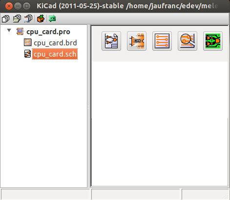
The main KiCad window consists of the project pane on the left and 5 buttons in the right pane to launch the following programs (Left to Right):
- EESchema – Schematic editor
- CVpcb – Components to modules (links schematics to footprints).
- PCBnew – PCB editor
- GerbView – Gerber viewer
- Bitmap2Component – Creates a component for EESchema or a footprint for PCBNew that shows a black and white picture.
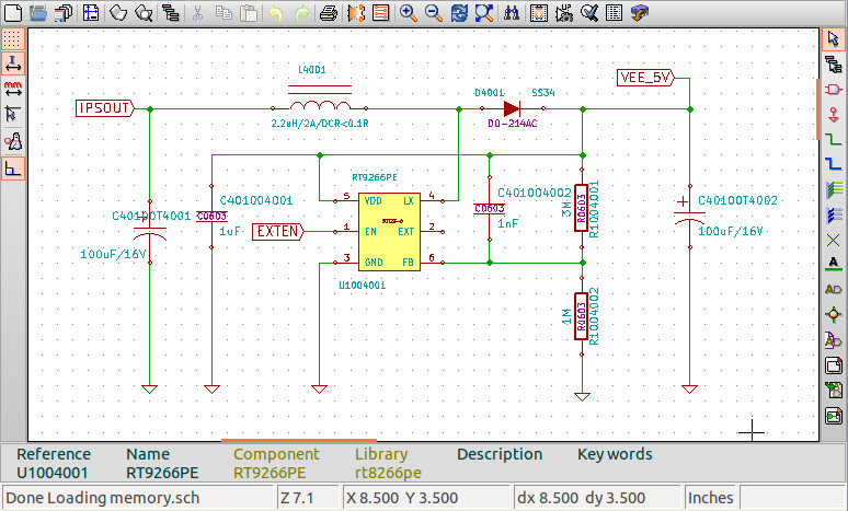
I’ve tried the Kicad project (Schematics + (incomplete) PCB layout) provided by Rhombus Tech for Allwinner A10 board, and EESchema appears to have many of the features available in Orcad. You can see a zoom one a part of the power section for AllWinner A10 board.

Now let’s try to import Beagleboard-xM design files in Kicad:
- Schematics (Orcad)
- Allegro files (PCB layout)
- Gerber files
After having downloaded and extracted the files, let’s create a new project in Kicad in the same directory. You’ll (joyfully) notice that Kicad detects automatically the layout file (.brd), but (sadly) its format is not recognized by Kicad.
Let’s take care of the schematics file first. You’ll need to have Cadence Orcad to convert the .dsn file to Electronic Definition Interchange Format (EDIF). Now let’s download edif2kicad, compile it and try to convert BB-xM_SCHEM_REVA3.EDF to Kicad format:
|
1 2 3 4 5 6 |
wget http://jaist.dl.sourceforge.net/project/edif2kicad/edif2kicad/edif2kicad-2008-04-01/edif2kicad-2008-04-01.tgz tar xzvf edif2kicad-2008-04-01.tgz cd edif2kicad make cd bbxm ../e2sch BB-xM_SCHEM_REVA3.EDF |
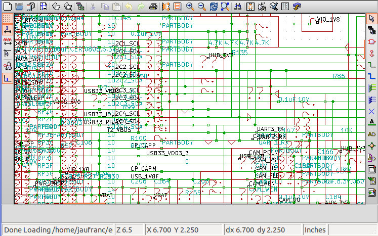
The program crash and failed to parse the EDF, so I had to delete 2 small items in the EDF file to create the sch files and all related libraries. I also had to delete one empty line in the .sch file and finally I was able to open the Beagleboard-xM “schematics” in Kicad.

As you can see, it did not go exactly according to plan. I’m not sure where the guilt is here, but edif2kicad has not been updated since 2008, and the EDIF file format may have been updated in the meantime. Or it’s simply that this type of conversion (Orcad to Kicad) cannot provide proper working files.
I’ve also been unable to find a way to convert an Allegro brd layout file (binary) to a Kicad brd layout file (text).
Kicad support .b*, .lgr and .pho gerber files, but those were not the format chosen for the Beagleboard-xM gerber files. I’ve tried to load drill files (.drl), but after a long wait, it failed with “Tool not defined”.
Kicad might be a good tool to start you own project from scratch, but you cannot expect to import exciting (Orcad/Allegro…) projects to Kicad without hassle or at all. If you design your hardware with Kicad, make sure the gerber files will be supported by the PCB manufacturer and follow GERBER-274-X.
To know more about Kicad, you can visit the official wiki. A list of Kicad libraries as well as a search engine for Kicad libaries are available. Finally, if you have any issues or questions, you can always on Kicad Yahoo Group.

Jean-Luc started CNX Software in 2010 as a part-time endeavor, before quitting his job as a software engineering manager, and starting to write daily news, and reviews full time later in 2011.
Support CNX Software! Donate via cryptocurrencies, become a Patron on Patreon, or purchase goods on Amazon or Aliexpress


