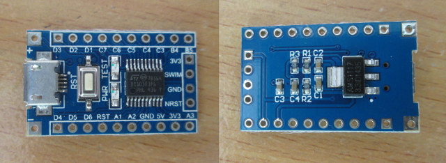
In January, I discovered there was such thing as a one dollar development board based on STMicro STM8S103F3P6 8-bit MCU with 1KB SRAM, 8KB flash, and 640 bytes EEPROM, some GPIOs as well as I2C, UART, SPI, ADC, and PWM signals. Links to documentation and source code were provided, but development tools were only Windows based. However, one of my reader informed me SDCC (Small Devices C Compiler) supported STM8, and development in Linux should be feasible. So I decided to buy the board on eBay for $1.62, as well as an ST_link V2 programmer for STM8 / STM32 for $4.52 in order to flash the firmware.
The board came pretty quickly, i.e. within 2 to 3 weeks.
But due to a lost package, the programmer took nearly 3 months to reach me, as the seller had to re-send after I failed to receive it within 2 months.
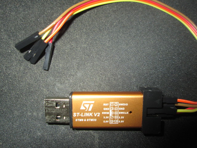
It comes with 4 wires that need to be connected to RST/NRST, 3.3V, SWIM, and GND. To do so, I had to solder a 4-pin header on the side of the board.
To get started with STM8 on Linux, I found some information on ColeVision website where they explained how to run Drystone on STM8/128-EVAL board using SDCC as the compiler, and stm8flash to program the board.
So I’ve given it a try on Ubuntu 14.04 with the simple goal of blinking the TEST LED on the board. sdcc is an Ubuntu package, so it’s pretty easy to install:
1 |
sudo apt-get install sdcc |
Let’s check the version and some more information:
sdcc --version
SDCC : mcs51/gbz80/z80/z180/r2k/r3ka/ds390/pic16/pic14/TININative/ds400/hc08/s08 3.3.0 #8604 (Dec 30 2013) (Linux)
That’s version 3.3.0 released in December 2013 and it lacks STM8 supports, but the latest version (sdcc v3.4.0) has been released in April 2014, and we can get it with a PPA, so let’s use that one instead:
1 2 3 4 |
sudo add-apt-repository ppa:laczik/ppa sudo apt-get update sudo apt-get remove sdcc sdcc-libraries sudo apt-get install sdcc |
If you are using Ubuntu 14.10 or greater, you’ll already get the latest version.
Let’s double check stm8 is indeed supported:
sdcc --version
SDCC : mcs51/z80/z180/r2k/r3ka/gbz80/tlcs90/ds390/pic16/pic14/TININative/ds400/hc08/s08/stm8 3.4.0 #8981 (Jan 10 2015) (Linux)
published under GNU General Public License (GPL)
Great! stm8 is now present in the list of supported MCUs.
For the next step was to install stm8flash tool to program the device:
1 2 3 4 |
git clone https://github.com/vdudouyt/stm8flash.git cd stm8flash make sudo make install |
Now I had to find some code samples to blink the LED. I started but checking the samples for ST Visual Programmer and IAR tools, combine with a modified version of Drystone source code, but I always had some issues with the header files, and it seems a bit more work than expected. But then I discovered that Valentin Dudouyt, stm8flash developer, also provided code samples in his github account, including a blinky sample:
1 2 |
git clone https://github.com/vdudouyt/sdcc-examples-stm8.git cd sdcc-examples-stm8 |
First, I tried to compile the samples, and they failed because sp_test.c was missing, so I edited the Makefile to remove sp_test.ihx, and build was successful. The LED on the board is connected to B5 GPIO, so at that point I had to check out STM8S103F3 datasheet to find out more about the registers used in the sample. The register map is in section 6.2 of the document, and I need to use three registers:
- PB_ODR – Port B data output latch register (Sets pin HIGH or LOW)
- PB_DDR – Port B data direction register (Sets direction to INPUT or OUTPUT)
- PB_CR1 – Port B control register 1
Since pin 5 correspond to 00100000 (0x20) I updated blinky.c sample as follows:
1 2 3 4 5 6 7 8 9 10 11 12 13 |
#include "stm8l.h" int main() { int d; // Configure pins PB_DDR = 0x20; PB_CR1 = 0x20; // Loop do { PB_ODR ^= 0x20; for(d = 0; d < 29000; d++) { } } while(1); } |
I typed make again to generate an updated firmware (blinky.ihx), and flash it as follows:
1 2 3 4 |
stm8flash -c stlinkv2 -p stm8s103 -w blinky.ihx Determine FLASH area Writing Intel hex file 189 bytes at 0x8000... OK Bytes written: 189 |
All good and the LED started blinking…
So now you should be able to write simple program to control other GPIOs, I2C, SPI, UART with the board. But if your program is a little more complex a debugger could be useful, and there’s Texane STLink working on Windows, Mac, and Linux, that can run gdbserver for STM32… But I tried it for STM8.
1 2 3 4 |
git clone https://github.com/texane/stlink cd stlink ./autogen.sh make -j8 |
Then I ran st-link:
1 2 3 4 |
./st-util 2015-04-13T16:44:34 INFO src/stlink-usb.c: -- exit_dfu_mode 2015-04-13T16:44:34 INFO src/stlink-common.c: Loading device parameters.... 2015-04-13T16:44:34 WARN src/stlink-common.c: unknown chip id! 0xe0042000 |
Hmmm, it does not look good, and sadly there’s no support for STM8 yet, as STM32 and STM8 use different interfaces (SWD vs SWIM).
So if you have troubles debugging your program, you may have to revert to Windows based tools, at least for now, unless you’re up for the task and want to add STM8 support to Texane.
Jean-Luc started CNX Software in 2010 as a part-time endeavor, before quitting his job as a software engineering manager, and starting to write daily news, and reviews full time later in 2011.
Support CNX Software! Donate via cryptocurrencies, become a Patron on Patreon, or purchase goods on Amazon or Aliexpress
You can change 15% or so on the board by going to http://www.ebay.com/itm/1PCS-STM8S103F3P6-ARM-STM8-Minimum-System-Development-Board-Module-for-Arduino/201243903693?_trksid=p2047675.c100005.m1851&_trkparms=aid%3D222007%26algo%3DSIC.MBE%26ao%3D1%26asc%3D20131003132420%26meid%3Dd31ab2e99b944989be2d4f8b520985d4%26pid%3D100005%26rk%3D2%26rkt%3D6%26sd%3D381123895681&rt=nc
Only $1.38 a saving of 24 cents (but 15% cheaper sounds a lot better) 🙂
I saw a AMS1117 voltage regulator on the back of the board. Does the chip runs in 3.3v or 5v?
The chip runs at DC3.3V
What is the USB port for? Reading the datasheet (quickly) seems to indicate that there is no USB device on that micro. Is it used for serial? If so, what’s doing the serial translation?
@Zygmunt Krynicki
Probably the USB is doing power only. It would be stupid for a manufacturer to have a USB stack on the chip, and not to use it in the bootloader to be able to reflash the chip with something else.
@zoobab
I guess it’s running at 3.3V, because the board is still running if I disconnect the USB port, and only connects it to the programmer that only provides 3.3V input.
@Zygmunt Krynicki
Just for power.
Use openocd! Its so simple and so efficient!
I actually used one of those stlink to flash a kinetis k10.
There is a qstlink that is quite sweet as well.
Con emulate PS3?
At least can run Super Street Figther 4?
Great article. Just got my board and programmer in the mail, solder headers and I was good to go. Compiled a new version of sdcc on Linux Mint 13 and was able to compile your test program and flashed it. LED blinks! One question, how did you know B5 was hooked up to the LED? Do you have the schematic or did you just trace it with a multimeter? The docs on eBay points to a link where the documentation are all in Chinese. Thanks!
@Jose
I think I found it in one of the schematics part of the documentation I linked @ http://www.cnx-software.com/2015/01/18/one-dollar-development-board/
I also double-checked with a multimeter, since other schematics connect the LED to PD3.
There are also a few tutorials (led counter, UART, benchmarks) at http://colecovision.eu/stm8/, currently for two evaluation boards (STM8L-DISCOVERTY and STM8/128-EVAL); I hope I’ll find to get the versions for the other boards up sometime.
Philipp
Hello, Really nice tutorial! very helpfull for a starter/make everything works ok project. I have also verified that the LED is on pin B5 with a mutlimeter. but even if i change the registers in code my LED doesn’t flash. I am thinking that my board is dead, but writing with stm8flash seems to be done with no errors, i would expect that to not happen at all with a dead chip, right? Do you have any pointers on what i should check next? or maybe a different .c file that tests the chip functionallity? P.S I did also check… Read more »
@Chris
The LED test is one of the most basic test to check whether the board is working.
I’d also assume you would not be able to flash a program is the board was dead.
If you have a USB logic analyzer you could connect it to several GPIO to find if any other pin level is changed with your program. Maybe also check the datasheet if there’s some info about boot behavior, like a clock or something that you could check.
@Jean-Luc Aufranc (CNXSoft)
I tried to maybe connect a new LED on A2 Pin, next to ground.
But the Datasheet is hard for my inexperienced eyes to read in order to decide what registers to use…
Can you help me a bit on that? i also though of changing the problem a bit, and keep the B5 high all the time.
Since i don’t own a logic analyzer ( yet ), maybe i can just keep it high and measure it with my mutlimeter?
Thanks for the fast reply 🙂
@Chris
I only spent one or two days on the platform, so I’m not exactly a specialist… 🙂
You could use a multimeter too to check the pin levels.
By the way, you are get an entry level logic analyzer for $5 to $10 these days. http://www.cnx-software.com/2015/09/27/using-usb123-usbee-ax-pro-5-usb-logic-analyzer-with-pulseview-in-linux/
Is there a way to programm this board without the st-link?
@Andrade
No. You really need the programmer. It costs about $5.
@Chris
My LED also does not blink. Did you ever figure this out?
Iv’e tested compiling and uploading with sdcc on Linux and Windows. Uploading works fine on both OS’s but the LED doesn’t blink.
Iv’e ordered a couple more from Ebay and Ali-express just to make sure its not the board.
@Andrew
I have seen at least two different schematics for this board with the LED connected to different GPIO pins.
So it’s possible your board is slightly different from mine.
You could always check which GPIO pin is turned on/off with a multimeter, or have the program turn on and off all GPIOs to check your board is working.
@Jean-Luc Aufranc (CNXSoft)
Well I tested the LED and the red one is working but not the green one. So idk if thats the only problem or if there is more.
I ordered 4 more from different places so I can confirm later when they arrive. Thanks for the tip.
Because of the price I bought a STM8S board to. I’m started with discription on your website (and other websites too). In the first it was a good entry point, but I spend a lot of time to discover out, that the adresses declared in stm8l.h are different to the adresses for stm8s. This was find out by reading the reference manual. For the GPIO it doesn’t matter, but if you want to use the USART1, it won’t work for receiving datas. Another thing is the clock setup. In your example the STM8S the CPU is clocked by internal 2… Read more »
/* ———————————————– Registeradressen fuer einen STM8S MCU Originaldatei war fuer einen STM8L – geaenderte Registeradressen fuer CLK 18.05.2016 R. Seelig ———————————————– */ // GPIO #define PA_ODR *(unsigned char*)0x5000 #define PA_IDR *(unsigned char*)0x5001 #define PA_DDR *(unsigned char*)0x5002 #define PA_CR1 *(unsigned char*)0x5003 #define PA_CR2 *(unsigned char*)0x5004 #define PB_ODR *(unsigned char*)0x5005 #define PB_IDR *(unsigned char*)0x5006 #define PB_DDR *(unsigned char*)0x5007 #define PB_CR1 *(unsigned char*)0x5008 #define PB_CR2 *(unsigned char*)0x5009 #define PC_ODR *(unsigned char*)0x500A #define PC_IDR *(unsigned char*)0x500B #define PC_DDR *(unsigned char*)0x500C #define PC_CR1 *(unsigned char*)0x500D #define PC_CR2 *(unsigned char*)0x500E #define PD_ODR *(unsigned char*)0x500F #define PD_IDR *(unsigned char*)0x5010 #define PD_DDR *(unsigned char*)0x5011 #define PD_CR1 *(unsigned char*)0x5012… Read more »
@Anton Fosselius
I checked http://openocd.org/ and saw no mention of the STM8 family, only the STM32. What can you use openocd for here please?
Hello! When I try to install stm8flash in lubuntu 16.10 LTS. In the terminal appears this error after typing ‘make’:
cc -g -O0 –std=gnu99 –pedantic
pkg-config --cflags libusb-1.0
-c -o stlink.o stlink.cPackage libusb-1.0 was not found in the pkg-config search path.
Perhaps you should add the directory containing `libusb-1.0.pc’
to the PKG_CONFIG_PATH environment variable
No package ‘libusb-1.0’ found
In file included from stlink.c:14:0:
pgm.h:6:21: fatal error: libusb.h: No existe el archivo o el directorio
compilation terminated.
: fallo en las instrucciones para el objetivo ‘stlink.o’
make: *** [stlink.o] Error 1
Someone who can help me! Thank you!
@Lazlo Lozla
You can see it says libusb-1.0 is missing, so you probably just have to install it:
That was the problem. I have to look more closely at the messages. Thank you!
Just got mine today.
I am trying to replace this:
http://hackaday.com/2011/02/06/versaloon-ported-to-stm8-and-stm32-discovery-boards/
@Peter
There are patches to add STM8 support to OpenOCD and GDB, and improve SDCC. https://stm8-binutils-gdb.sourceforge.io/ (I haven’t tested them yet)
@zoobab
I’ve never heard of versaloon, but looking at that page, it makes me think about the Black Magic Probe. ( https://github.com/blacksphere/blackmagic/wiki ). The firmware can also be flashed to the cheap ST-Link clones as in the picture in the article. However, there is no STM8 support, only ARM support. GDB directly connects to the Black Magic Probe, without the need of OpenOCD. However, even though GDB itself seems to work fine with BMP, I haven’t gotten eclipse to work with it yet.
I tried on Windows and success
– got sdcc and stm8flash and libusb-1.0.dll from https://github.com/tenbaht/sduino-windowstools
– add sduino-windowstools-master\tools\bin to %PATH%
– install stlink driver (en.stsw-link009.zip)
– my module is locked, so https://github.com/vdudouyt/stm8flash/files/372158/optdefault.bin.txt
>stm8flash.exe -c stlinkv2 -p stm8s103f3 -s opt -w optdefault.bin.txt
– got that blinky.c and stm8l.h
>sdcc.exe -lstm8 -mstm8 –out-fmt-ihx blinky.c
>stm8flash.exe -c stlinkv2 -p stm8s103f3 -w blinky.ihx
My flash is locked, so (https://github.com/vdudouyt/stm8flash/issues/38)
echo “00 00 ff 00 ff 00 ff 00 ff 00 ff” | xxd -r -p > factory_defaults.bin
stm8flash -c stlinkv2 -p stm8s103f3 -s opt -w factory_defaults.bin