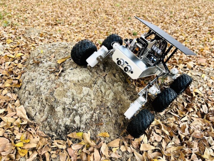
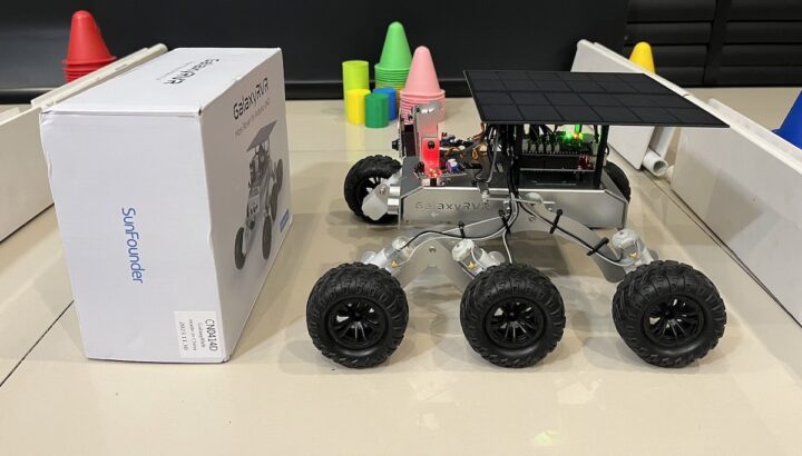
SunFounder sent us a GalaxyRVR 6-wheel robot for review. It looks like NASA’s Mars Rover robots but targets the education market with an Arduino UNO R3 compatible board and an ESP32-CAM board for WiFi connectivity and video capture.
The GalaxyRVR robot kit can transmit video signals over WiFi to explore planet Earth with your mobile device or tablet and the camera can be adjusted up and down thanks to a servo motor. The robot gets its power from a solar panel coupled with a battery and features sensors such as obstacle avoidance and ultrasonic modules.
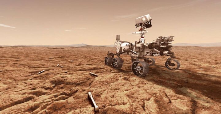
NASA’s Mars Rover exploration robots
NASA is currently using the Perseverance rover, also known as Percy, as the latest planetary exploration robot to land on Mars. It is designed to explore the Jezero Crater as part of NASA’s Mars 2020 mission. In addition to its scientific instruments, Perseverance also carries Ingenuity, a small experimental Martian helicopter.
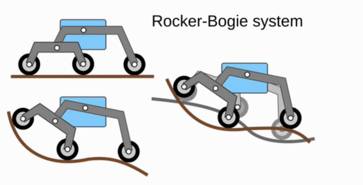
SunFounder GalaxyRVR robot kit simulates a moving structure with the same Rocker-Bogie Mechanism system used in NASA’s Mars rover with the ability to explore all types of terrains. Whether it’s a rocky mountain, a sandy beach, or a grassy field, a vibration-dampening system helps the robot move smoothly.
What’s a Rocker-Bogie system?
The Rocker-Bogie system is a mechanism that can overcome environmental obstacles and has been designed to accommodate the unpredictable topography of Mars including steep slopes and large boulders. The system can cross obstacles and make use of its six wheels to navigate difficult terrain and explore different areas of the planet.
SunFounder GalaxyRVR kit unboxing and assembly
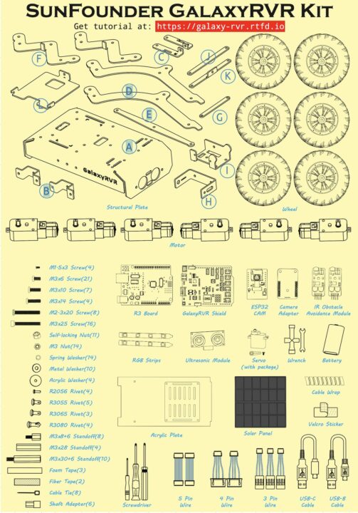
The SunFounder GalaxyRVR robot kit comes with over 300 pieces (including screws) which users must learn to assemble themselves. The instructions can be found on GitHub (PDF).
People who prefer video tutorials can check out the assembly instructions in the video below.
We’ll now go into detail about the key components of the kit. This is quite long, so you can jump to the programming part if you want to carry on with the review without knowing the details of each component.
SunFounde R3: GalaxyRVR control board
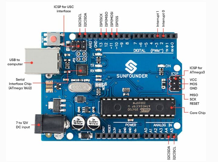
The SunFounder R3 is an ATmega328P-based microcontroller board with 14 digital I/O ports (6 of which can be used as PWM outputs), and 6 analog input pins. It connects to a computer via a USB device cable to upload a program and can be powered with an AC-to-DC adapter or a 7 -12V battery to get started.
It’s basically a clone of the popular Arduino UNO R3.
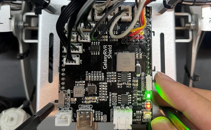
SunFounder GalaxyRVR shield
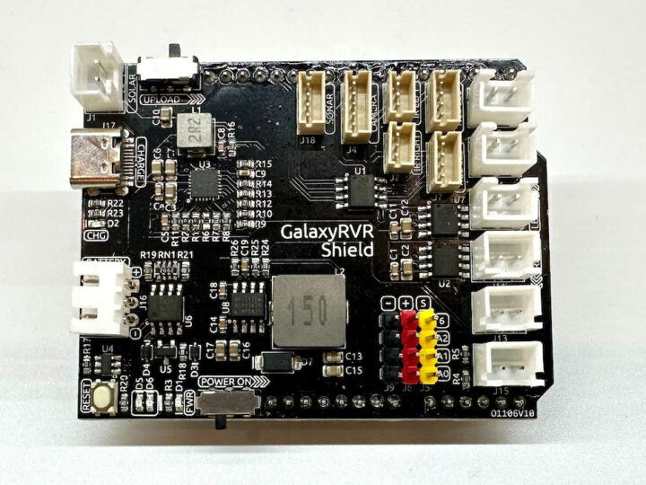
The GalaxyRVR shield is an expansion board that fits on top of the SunFounder S3 Arduino board and features connectors for motors, RGB lights, IR obstacle avoidance sensors, the ESP32-CAM board, and ultrasonic modules.
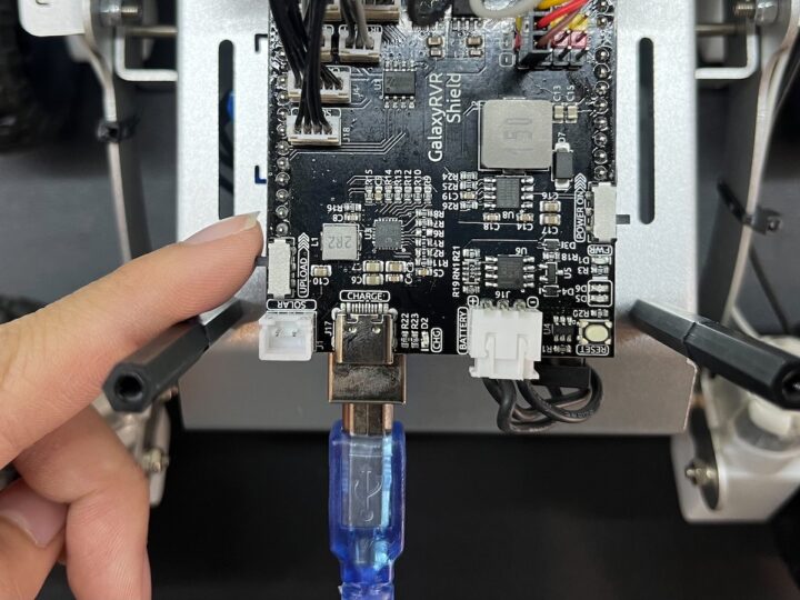
The expansion board also has a charging circuit and a PH2.0-3P connector for a LiPo battery. A full charge for an 18,650 7.4V 2,000mAh battery takes approximately 130 minutes.
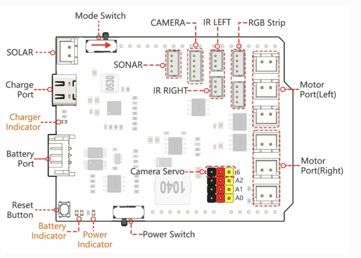
List of ports on the GalaxyRVR shield:
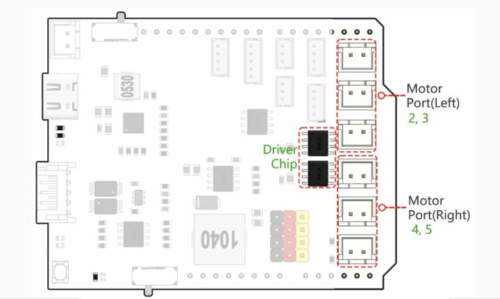
- Motor Port
- Motor ports (right) – 3x motors can be connected with all 3 motors controlled by the same set of signal pins 2 and 3.
- Motor ports (Left) – 3x motors can be connected with all 3 motors controlled by the same set of signal pins 4 and 5.
- Port Type: XH2.54, 2P.
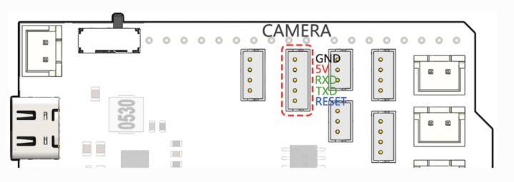
- Camera I/F – 5-pin connector for camera adapter board port
- Camera Servo – The servo on the camera is connected to. The brown wire connects to “-”, the red wire connects to “+”, and the yellow wire connects to pin 6.
- Sensors
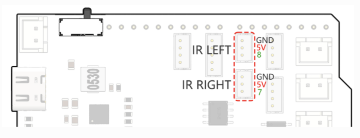
- LEFT/RIGHT IR – 3-pin connectors for IR obstacle avoidance modules. The left obstacle avoidance module is connected to pin 8, the right obstacle avoidance module is connected to pin 7.
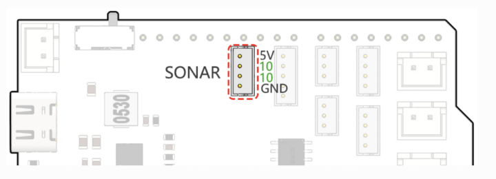
- SONAR – 4-pin connector for both Trig & Echo pins
- Misc
- Reset Button – Press this button to reset the program on the Arduino board.
- Indicators
- Charge Indicator – Glows red when the shield is charging through the USB-C port.
- Power Indicator – Glows green when the power switch is in the “ON” position.
- Battery Indicator – Two orange indicators represent different battery levels. They flash during charging and turn off when the battery needs charging.
- Power Switch – Slide to ON to power on the GalaxyRVR
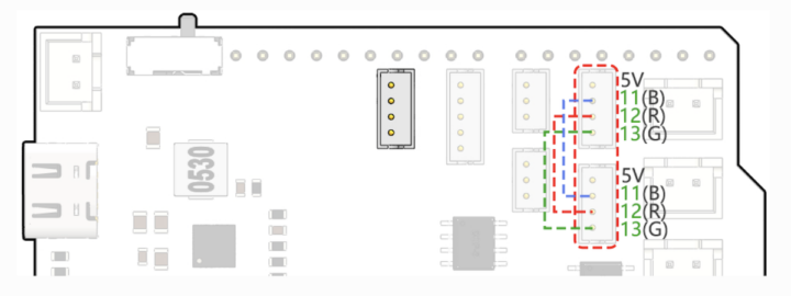
- RGB Strip – For connecting 2x RGB LED strips
- Mode Switch – The ESP32-CAM and the Arduino board share the same RX (receive) and TX (transmit) pins. So, when you’re uploading code, you’ll need to toggle this switch to the right side to disconnect the ESP32-CAM to avoid any conflicts or potential issues.
- Power
- Charge Port – 5V/2A USB-C port used to charge the battery
- Battery Port – 6.6V~8.4V PH2.0 3-pin power input for a battery powering both the GalaxyRVR Shield and Arduino board
- SOLAR – 2-pin connector for the solar panel
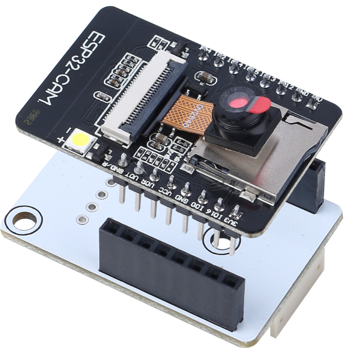
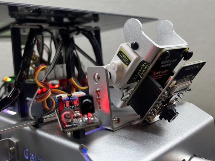
ESP32-CAM
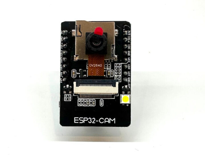
The ESP32-CAM is a small OV2560 camera module with an ESP32-S WiFi module and a microSD card slot for storing images taken with the camera. It measures 27 x 40.5 x 4.5 mm and consumes only 6 mA.
ESP32-CAM adapter board
The ESP32-CAM adapter board is an expansion board for the ESP32-CAM used to connect it to the SunFounder GalaxyRVR robot.
The ESP32-CAM adapter board connects to the SunFounder GalaxyRVR expansion board through a 5-pin ZH 1.5 connector.
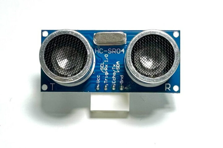
HC-SR04 ultrasonic module
The GalaxyRVR robot also features an off-the-shelf HC-SR04 ultrasonic distance sensor with a range from 2 cm to 400 cm and an accuracy range of up to 3 mm.
The ultrasonic module port is connected tot the 5-pin connector on the SunFounder GalaxyRVR shield.
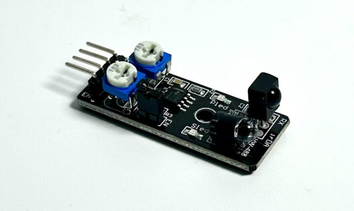
IR obstacle avoidance module
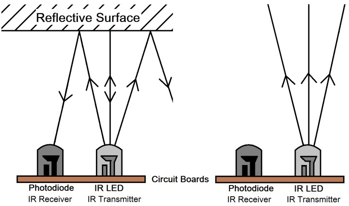
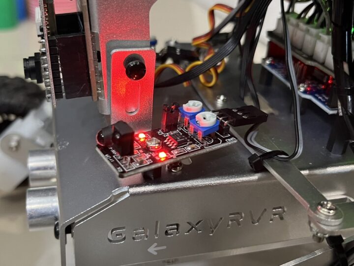
The IR obstacle avoidance module is an infrared obstacle avoidance module that can detect objects ahead. It is generally used in robots. The detection range is from 2 cm to 40 cm, and objects of different colors have different levels of reflectivity. Therefore, the darker the object, the shorter the detection distance.
The IR obstacle avoidance module consists of one IR transmitter and one IR receiver. It emits an infrared light signal and when the emitted infrared light hits an object, it is reflected to the photoreceptor. When the light on the sensor board is detected, the status will be displayed, and it will send a low-level signal to the OUTPUT pin.
The two IR obstacle avoidance modules are connected to the SunFounder GalaxyRVR expansion board through the 3-pin IR LEFT and IR RIGHT connectors.
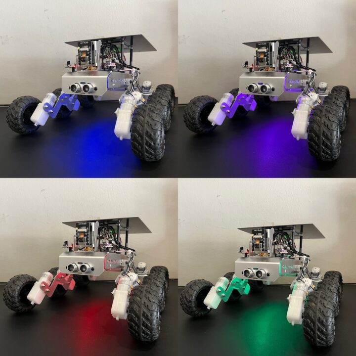
RGB LED strip
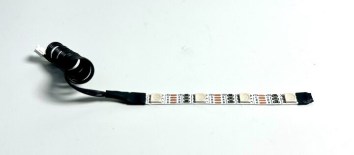
Two RGB LED strips with four R5050 RGB LEDs are part of the kit.
They are connected to two 4-pin connected on the SunFounder GalaxyRVR shield.
TT Gear Motor
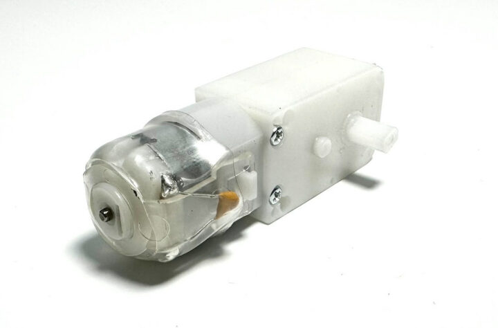
Each wheel is attached to a TT gear motor. All gears are housed in durable plastic construction with a gear ratio of 1:120 and two 250mm wires with XH2.54-2P connectors (3V DC).
TT motor specifications:
- Operating voltage – 3V ~ 4.5V DC
- Number of shafts – Single shaft Gear ratio: 1:120
- No-load current – 130mA
- Rotational speed under load – 38rpm ±8%rpm
- Starting voltage – 2V (maximum) when no load
- Output torque – 3V ≥ 1.2 kgf.cm
- Service life – 70-120H
- Direction of rotation – two directions
- Dimensions – 70 x 22.5 x 36.6 mm
- Wire – gray and black 24 AWG, length 250 mm.
- Connector – White XH2.54-2P
- Weight – 28.5 grams
Each TT gear motor is connected through a 2-pin connector on the SunFounder Galaxy RVR shield with three blocks of connectors for left and right motors.
Wheels
The SunFounder GalaxyRVR robot comes with 6 wheels each with a diameter of 75 mm and a width of 37 mm made of synthetic rubber material suitable to glide on all types of floors.
Servo Motor
The servo motor is used to control the angular position of the camera with high precision. The servo motor features a metal gear, takes 4.8 to 7.4 volts DC input, and can rotate by up to 180 degrees.
It is connected through a 3-pin connector to the GalaxuRVR shield.
Solar panel
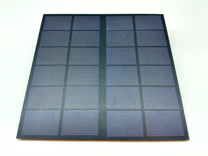
A solar panel is a device that converts solar energy into electrical energy. It consists of a photovoltaic (PV) cell, which is made of semiconductor materials such as silicon. When sunlight hits the PV cell, it knocks electrons away from the atoms, and these electrons flow through the cell generating an electrical current. Solar panels can be used to produce electricity for a variety of purposes. This includes powering homes, businesses, and even entire communities. It is a clean, renewable energy source that can help reduce our dependence on fossil fuels.
Solar panel features
- Output power – 6V/660mA
- Time to fully charge the battery – 7.2 hrs (theoretical, assuming bright sunlight)
- Dimensiosn – 170 x 170mm
- Wire – gray and black 24AWG 200mm
- Connector – White XH2.54-2P
Battery
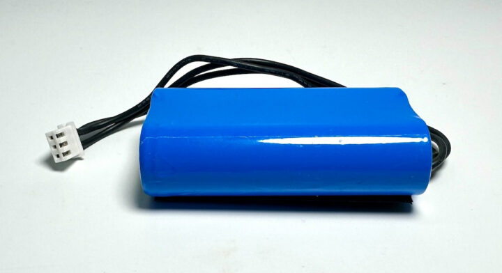
The battery pack is produced by SunFounder themselves. It consists of two 18,650 batteries with a capacity of 2000mAh. The connector is a 3-pin XH2.54 connector designed to be plugged into the GalaxyRVR shield.
Key features
- Battery charging – 5V/2A
- Battery output – 5V/5A
- Battery capacity – 2x 3.7V 2,000mAh
- Battery life – 90 minutes
- Battery charging time – 130 minutes
- Connector – 3-pin XH2.54
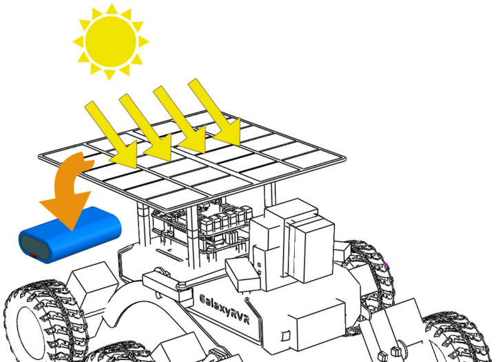
SunFounder GalaxyRVR robot energy management
The main components of this power system are batteries and the solar panel taking power from the sun. Working in tandem, the GalaxyRVR robot can work at all hours of the day and night.
Getting started with SunFounder GalaxyRVR robot
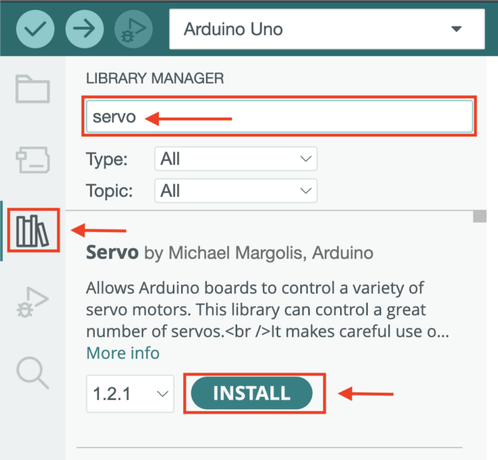
The GalaxyRVR robot can be programmed in the C language with the Arduino IDE. The SunFounder GalaxyRVR robot required three libraries. Users need to go to the Library Manager to install them starting with the Servo library.
Repeat the same for the “SoftPWM” and “SunFounder AI Camera” libraries. Uploading programs to the SunFounder S3 board requires moving the upload switch to the right to disconnect from the ESP32-CAM.
Now slide the power switch to “ON” to turn on the GalaxyRVR robot.
Testing the RGB LED lights
To test the RGB LEDs, we performed a series of cycles to change the colors.
Here’s the code for the test program:
|
1 2 3 4 5 6 7 8 9 10 11 12 13 14 15 16 17 18 19 20 21 22 23 24 25 26 27 28 29 30 31 32 33 34 35 36 37 38 39 40 41 42 |
#include <SoftPWM.h> // Include the SoftPWM library // Define the pin numbers for the RGB strips const int bluePin = 11; const int redPin = 12; const int greenPin = 13; /* Calibrate brightness */ #define R_OFFSET 1.0 #define G_OFFSET 0.25 #define B_OFFSET 0.45 void setup() { SoftPWMBegin(); // Initialize software-based PWM on all pins } void loop() { // Set different colors with a delay of 1 second (1000 ms) in between setColor(255, 0, 0); // Set the color to red delay(1000); setColor(255, 128, 0); // Set the color to orange delay(1000); setColor(255, 255, 0); // Set the color to yellow delay(1000); setColor(0, 255, 0); // Set the color to green delay(1000); setColor(0, 0, 255); // Set the color to blue delay(1000); setColor(0, 255, 255); // Set the color to lightblue delay(1000); setColor(255, 0, 255); // Set the color to purple delay(1000); setColor(255, 255, 255); // Set the color to white delay(1000); } // Define a function to set color void setColor(int red, int green, int blue) { SoftPWMSet(redPin, red * R_OFFSET); // Set red color SoftPWMSet(greenPin, green * G_OFFSET); // Set green color SoftPWMSet(bluePin, blue * B_OFFSET); // Set blue color } |
Servo motor control test program to raise and lower the ESP32 camera.
We tested the servo motor by writing code adjusting the camera from 0 degrees to 180 degrees delaying the degree shift every 100 milliseconds.
Sample code:
|
1 2 3 4 5 6 7 8 9 10 11 12 13 14 15 16 17 |
#include <Servo.h> Servo myServo; // create a servo object void setup() { myServo.attach(6); // attaches the servo on pin 6 Serial.begin(9600); // initialize serial communication at a baud rate of 9600 } void loop() { for (int i = 0; i <= 180; i++) { // loop from 0 to 180 degrees Serial.print("The angle is: "); // print angle information Serial.println(i); // print the current angle value myServo.write(i); // control the servo to move to the current angle delay(100); // delay for 100 milliseconds } } |
SunFounder Galaxy RVR robot’s movement testing
We then wrote a sample program to move forward, turn left, turn right, back, and stop the robot, with sequenced commands.
Sample code:
|
1 2 3 4 5 6 7 8 9 10 11 12 13 14 15 16 17 18 19 20 21 22 23 24 25 26 27 28 29 30 31 32 33 34 35 36 37 38 39 40 41 42 43 44 45 46 47 48 49 50 51 52 53 54 55 56 57 58 59 60 61 62 63 64 65 66 67 68 69 70 71 72 73 74 75 76 77 78 79 80 81 82 |
#include <SoftPWM.h> // Define the pins of motors const int in1 = 2; const int in2 = 3; const int in3 = 4; const int in4 = 5; void setup() { // Initialize SoftPWM SoftPWMBegin(); } void loop() { moveForward(200); // Move the Rover forward delay(1000); turnLeft(200); // Turn the Rover to the left delay(1000); moveForward(200); // Move the Rover forward delay(1000); turnLeft(200); // Turn the Rover to the left delay(1000); moveForward(200); // Move the Rover forward delay(1000); moveBackward(200); // Move the Rover backward delay(1000); turnRight(200); // Turn the Rover to the right delay(1000); stopMove(); // Stop the Rover delay(5000); } void moveForward(int speed) { // Set the left motors rotate counterclockwise SoftPWMSet(in1, speed); SoftPWMSet(in2, 0); // Set the right motors rotate clockwise SoftPWMSet(in3, 0); SoftPWMSet(in4, speed); } void moveBackward(int speed) { // Set the left motors rotate clockwise SoftPWMSet(in1, 0); SoftPWMSet(in2, speed); // Set the right motors rotate counterclockwise SoftPWMSet(in3, speed); SoftPWMSet(in4, 0); } void turnLeft(int speed) { // Set al motors to rotate clockwise SoftPWMSet(in1, 0); SoftPWMSet(in2, speed); SoftPWMSet(in3, 0); SoftPWMSet(in4, speed); } void turnRight(int speed) { // Set all motors to rotate counterclockwise SoftPWMSet(in1, speed); SoftPWMSet(in2, 0); SoftPWMSet(in3, speed); SoftPWMSet(in4, 0); } void stopMove() { // Stop all the motors SoftPWMSet(in1, 0); SoftPWMSet(in2, 0); SoftPWMSet(in3, 0); SoftPWMSet(in4, 0); } |
Ultrasonic sensor testing
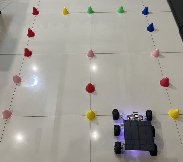
We wrote a sketch to read the value of the ultrasonic sensor and if the condition that the sensor reads more than 50 centimeters, the robot moves forward, while if the sensor reads less than 15 centimeters and more than 1 centimeter, the robot reverses for 500 milliseconds and turns left for 1.5 seconds.
Arduino sketch:
|
1 2 3 4 5 6 7 8 9 10 11 12 13 14 15 16 17 18 19 20 21 22 23 24 25 26 27 28 29 30 31 32 33 34 35 36 37 38 39 40 41 42 43 44 45 46 47 48 49 50 51 52 53 54 55 56 57 58 59 60 61 62 63 64 65 66 67 68 69 70 71 72 73 74 75 76 77 78 79 80 81 82 83 84 85 86 87 88 89 90 91 92 93 |
#include <SoftPWM.h> // Define the pin for the ultrasonic module #define ULTRASONIC_PIN 10 // Define the pins of motors const int in1 = 2; const int in2 = 3; const int in3 = 4; const int in4 = 5; void setup() { // Initialize SoftPWM SoftPWMBegin(); //Serial.begin(9600); } void loop() { // Read distance from ultrasonic sensor float distance = readSensorData(); //Serial.println(distance); // Output distance for debugging // Control rover based on distance reading if (distance > 50) { // If it's safe to move forward moveForward(200); } else if (distance < 15 && distance > 1) { // If there's an obstacle close moveBackward(200); delay(500); // Wait for a while before attempting to turn backLeft(150); delay(1000); } else { // For distances in between, proceed with caution moveForward(150); } } float readSensorData() { // A 4ms delay is required, otherwise the reading may be 0 delay(4); //Set to OUTPUT to send signal pinMode(ULTRASONIC_PIN, OUTPUT); // Clear the trigger pin digitalWrite(ULTRASONIC_PIN, LOW); delayMicroseconds(2); // Trigger the sensor by sending a high pulse for 10us digitalWrite(ULTRASONIC_PIN, HIGH); delayMicroseconds(10); // Set the trigger pin back to low digitalWrite(ULTRASONIC_PIN, LOW); //Set to INPUT to read pinMode(ULTRASONIC_PIN, INPUT); // pulseIn returns the duration of the pulse on the pin float duration = pulseIn(ULTRASONIC_PIN, HIGH); // Calculate the distance (in cm) based on the speed of sound (340 m/s or 0.034 cm/us) float distance = duration * 0.034 / 2; return distance; } void moveForward(int speed) { // Set the left motors rotate counterclockwise SoftPWMSet(in1, speed); SoftPWMSet(in2, 0); // Set the right motors rotate clockwise SoftPWMSet(in3, 0); SoftPWMSet(in4, speed); } void moveBackward(int speed) { // Set the left motors to rotate clockwise SoftPWMSet(in1, 0); // Stop SoftPWMSet(in2, speed); // Full speed // Set the right motors to rotate counterclockwise SoftPWMSet(in3, speed); // Full speed SoftPWMSet(in4, 0); // Stop } // Function to turn to the back left void backLeft(int speed) { SoftPWMSet(in1, 0); SoftPWMSet(in2, 0); SoftPWMSet(in3, speed); SoftPWMSet(in4, 0); } |
Obstacles avoidance with the IR obstacle avoidance modules
We then wrote another program to read the value from the right and left obstacle avoidance modules. If the right IR sensor detects an object and the left IR sensor does not detect an object, the robot turns backward to the right at a speed of 150 and if the right IR sensor cannot detect anything, but the left IR sensor finds the object, the robot turn backward left at a speed of 150. If both sensors detect an object, the robot reverses at a speed of 150. In all other conditions, the robot moves forward.
Sample code:
|
1 2 3 4 5 6 7 8 9 10 11 12 13 14 15 16 17 18 19 20 21 22 23 24 25 26 27 28 29 30 31 32 33 34 35 36 37 38 39 40 41 42 43 44 45 46 47 48 49 50 51 52 53 54 55 56 57 58 59 60 61 62 63 64 65 66 67 68 69 70 71 72 73 74 75 76 77 |
#include <SoftPWM.h> // Define the pins of motors const int in1 = 2; const int in2 = 3; const int in3 = 4; const int in4 = 5; // Define the pins for the IR modules #define IR_RIGHT 7 #define IR_LEFT 8 void setup() { // Initialize SoftPWM SoftPWMBegin(); // Set the IR module pins as inputs pinMode(IR_RIGHT, INPUT); pinMode(IR_LEFT, INPUT); } void loop() { // Read values from IR sensors int rightValue = digitalRead(IR_RIGHT); int leftValue = digitalRead(IR_LEFT); // Based on IR sensor readings, control rover's movements if (rightValue == 0 && leftValue == 1) { // Right path blocked backRight(150); } else if (rightValue == 1 && leftValue == 0) { // Left path blocked backLeft(150); } else if (rightValue == 0 && leftValue == 0) { // Both paths blocked moveBackward(150); } else { // Paths clear moveForward(150); } delay(100); } // Function to move the rover backward void moveBackward(int speed) { // Set the left motors to rotate clockwise SoftPWMSet(in1, 0); // Stop SoftPWMSet(in2, speed); // Full speed // Set the right motors to rotate counterclockwise SoftPWMSet(in3, speed); // Full speed SoftPWMSet(in4, 0); // Stop } void moveForward(int speed) { // Set the left motors rotate counterclockwise SoftPWMSet(in1, speed); SoftPWMSet(in2, 0); // Set the right motors rotate clockwise SoftPWMSet(in3, 0); SoftPWMSet(in4, speed); } // Function to turn to the back right void backRight(int speed) { SoftPWMSet(in1, 0); SoftPWMSet(in2, speed); SoftPWMSet(in3, 0); SoftPWMSet(in4, 0); } // Function to turn to the back left void backLeft(int speed) { SoftPWMSet(in1, 0); SoftPWMSet(in2, 0); SoftPWMSet(in3, speed); SoftPWMSet(in4, 0); } |
Sending images from the camera to a Web Browser
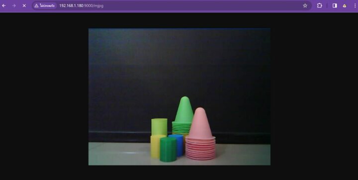
Our next test program aims to stream images from the ESP32-CAM board in a Web Browser. We must first connect to a WiFi network and open the Web Browser using the IP address of the robot (e.g. 192.168.1.xxx).
Arduino sketch:
|
1 2 3 4 5 6 7 8 9 10 11 12 13 14 15 16 17 18 19 20 21 22 23 24 25 26 27 28 29 30 31 32 33 34 35 36 37 38 |
#include "SunFounder_AI_Camera.h" // Wifi configuration and credentials // AP Mode // #define WIFI_MODE WIFI_MODE_AP // #define SSID "GalaxyRVR" // #define PASSWORD "12345678" // STA Mode #define WIFI_MODE WIFI_MODE_STA #define SSID "YOUR SSID" #define PASSWORD "YOUR PASSWORD" // Device configuration #define NAME "GalaxyRVR" // Device name #define TYPE "AiCamera" // Device type #define PORT "8765" // Port for the SunFounder Controller APP // Create AiCamera Object AiCamera aiCam = AiCamera(NAME, TYPE); void setup() { // Initialize Serial(optional, if you need to debug) Serial.begin(115200); // Initialize AiCamera aiCam.begin(SSID, PASSWORD, WIFI_MODE, PORT); // Set command timeout (optional, default 100) aiCam.setCommandTimeout(100); } void loop() { // AiCamera loop. must put it in loop(). And more importantly, every time loop // runs, a perioad of data send receive runs, so loop must be fast enough. // or it will be laggy or even stuck by other code. aiCam.loop(); } |
Controlling the SunFounder GalaxyRVR robot through a mobile app
SunFonuder provides an Arduino sketch to let users control the GalaxyRVR robot from an app.
Arduino sketch:
|
1 2 3 4 5 6 7 8 9 10 11 12 13 14 15 16 17 18 19 20 21 22 23 24 25 26 27 28 29 30 31 32 33 34 35 36 37 38 39 40 41 42 43 44 45 46 47 48 49 50 51 52 53 54 55 56 57 58 59 60 61 62 63 64 65 66 67 68 69 70 71 72 73 74 75 76 77 78 79 80 81 82 83 84 85 86 87 88 89 90 91 92 |
#include "SunFounder_AI_Camera.h" #include <Servo.h> #include <SoftPWM.h> // Create a Servo object Servo myServo; // Wifi configuration and credentials // In AP Mode #define WIFI_MODE WIFI_MODE_AP #define SSID "GalaxyRVR" #define PASSWORD "12345678" // Device configuration #define NAME "GalaxyRVR" // Device name #define TYPE "AiCamera" // Device type #define PORT "8765" // Port for the SunFounder Controller APP // Create an AiCamera object AiCamera aiCam = AiCamera(NAME, TYPE); // Define the pins of motors const int in1 = 2; const int in2 = 3; const int in3 = 4; const int in4 = 5; void setup() { // Initialize Serial for debugging Serial.begin(115200); // Attach the servo on pin 6 myServo.attach(6); // Initialize the AiCamera aiCam.begin(SSID, PASSWORD, WIFI_MODE, PORT); // Set the function to execute when data is received aiCam.setOnReceived(onReceive); // Set the command timeout aiCam.setCommandTimeout(100); // Initialize SoftPWM SoftPWMBegin(); // Stop all the motors SoftPWMSet(in1, 0); SoftPWMSet(in2, 0); SoftPWMSet(in3, 0); SoftPWMSet(in4, 0); } void loop() { // Must include this in the loop. Handles data sending and receiving from the Controller. aiCam.loop(); } // Function to execute when data is received from the Controller void onReceive() { // Get the value of the slider in region D int16_t sliderD = aiCam.getSlider(REGION_D); // Move the servo to the angle indicated by the slider myServo.write(int(sliderD)); // Get the throttle values for the left and right int throttle_L = aiCam.getThrottle(REGION_K); int throttle_R = aiCam.getThrottle(REGION_Q); // Set the power for the motors carSetMotors(throttle_L, throttle_R); } // Function to set the power of the motors void carSetMotors(int8_t power_L, int8_t power_R) { // Set power for the left motor if (power_L >= 0) { SoftPWMSet(in1, map(power_L, 0, 100, 0, 255)); SoftPWMSet(in2, 0); } else { SoftPWMSet(in1, 0); SoftPWMSet(in2, map(power_L, 0, -100, 0, 255)); } // Set power for the right motor if (power_R >= 0) { SoftPWMSet(in3, 0); SoftPWMSet(in4, map(power_R, 0, 100, 0, 255)); } else { SoftPWMSet(in3, map(power_R, 0, -100, 0, 255)); SoftPWMSet(in4, 0); } } |
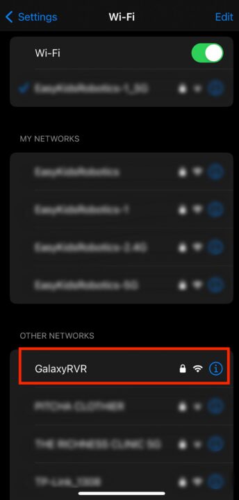
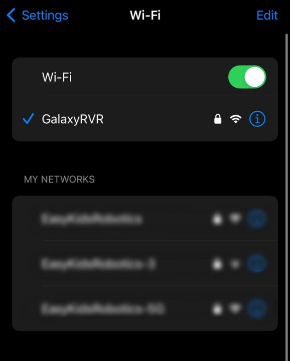
Once the program is running in the robot, you can go to your phone to find the GalaxyRVR SSID defined in the program.
Connect to it with the password in the program, in our case: 12345678.
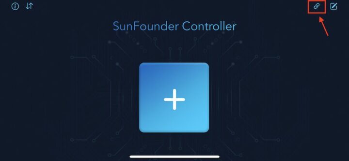
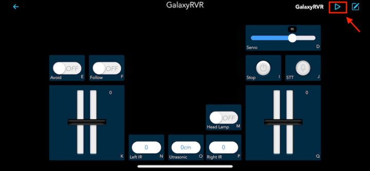
Now find the “SunFounder Controller” in the Google Play store or Apple App Store, and install it. Now start the app and tap on the connect icon in the top right corner.
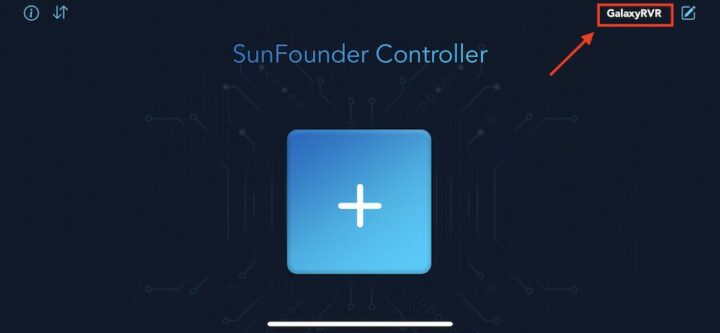
After a successful connection to the robot, the name “GalaxyRVR” will appear.
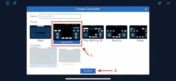
Now press the + icon and select the user interface “GalaxyRVR” to create a new controller.
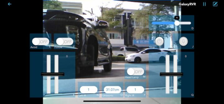
Finally, tap on the Play icon in the top right corner to display the video streaming from the ESP32-CAM module.
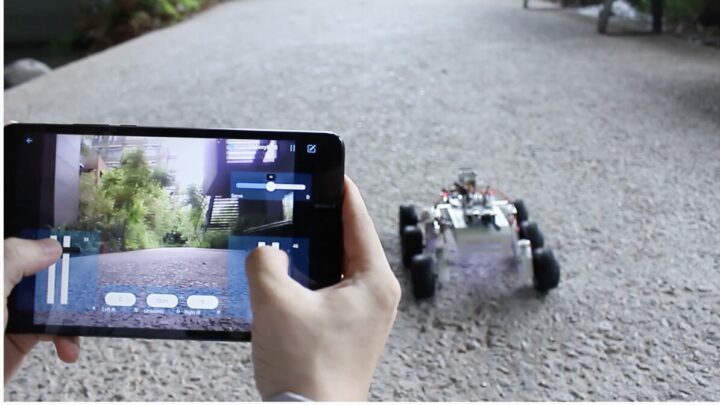
You can now control all functions of the GalaxyRVR robot such as showing RGB lights, controlling movements, avoiding obstacles, and even commanding the robot by voice. The video review below shows how it all works.
Sunfounder GalaxyRVR robot video review
Conclusion
SunFounder GalaxyRVR robot is quite a novelty as most wheel-based robots simply emulate a car. But with this robot, students can learn about the Rocker-Bogie system used in NASA’s planetary exploration rover robots. It also features many functions such as obstacle avoidance, RGB LED strips., and live camera streaming over WiFi. Students can also learn about Arduino programming besides robotics concepts. Further details may be found in the documentation.
We would like to thank SunFounder for sending us the GalaxyRVR Mars rover robot kit for review. The GalaxyRVR robot kit can be purchased for $129.99 on the company’s online store or Amazon US.
CNXSoft: This article is a translation of the original review on CNX Software Thailand by Karnjonsak Janjam, edited by Suthinee Kerdkaew

Jean-Luc started CNX Software in 2010 as a part-time endeavor, before quitting his job as a software engineering manager, and starting to write daily news, and reviews full time later in 2011.
Support CNX Software! Donate via cryptocurrencies, become a Patron on Patreon, or purchase goods on Amazon or Aliexpress


