Dusun IoT DSOM-020R PX30 is a development board based on the company’s 1.3GHz Rockchip PX30K quad-core Cortex-A35 module of the same name designed for industrial applications that emphasize reliability and power efficiency.
The board comes with various ports and expansion capabilities with support for monitors, microphones, and sensors through its carrier board in order to create prototypes and develop software before integrating the SOM DSOM-020 PX30 system-on-module into your own custom carrier board and product.
As the company stipulates on the website, the development board is suitable for AIoT equipment, vehicle control, gaming platforms, smart displays, medical equipment, vending machines, and industrial computers. Let’s start the review with an unboxing of the DSOM-020R PX30 development board to find out more.
DSOM-020R PX30 development board unboxing
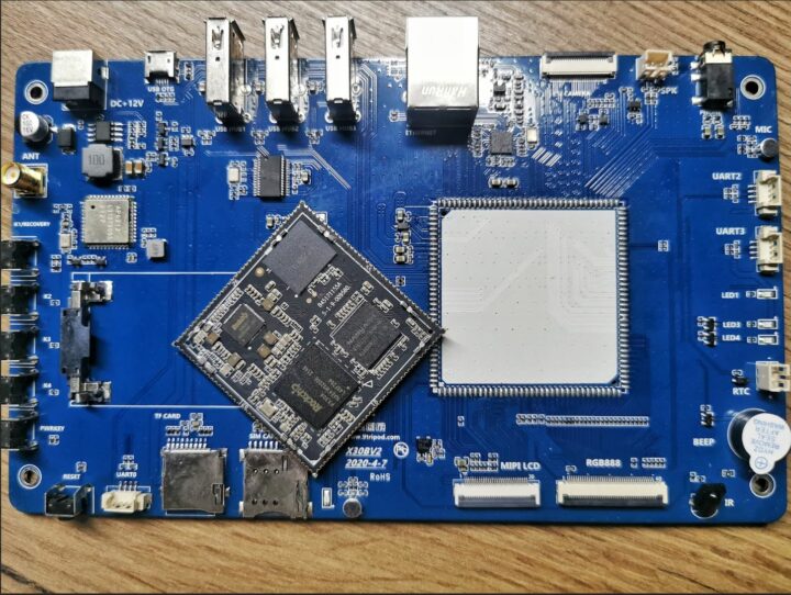
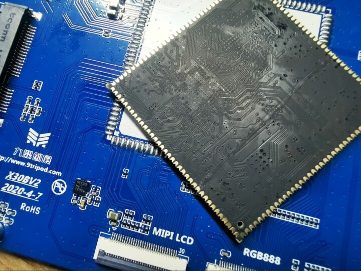
Dusun IoT sent us a basic kit of the DSOM-020R PX30 development board for review with a carrier board, the DSOM-020 PX30 system-on-module module, a USB2Serial debug board, a USB cable, and 12V/2A power adapter. We were initially taken aback as the module was not soldered to the carrier board.
But instead of returning the board, we eventually decided to solder it ourselves to the carrier board to carry on with the review. Here’s what the complete kit we received looks like after soldering the module.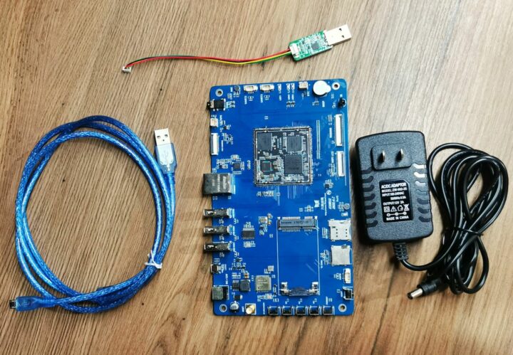
Hardware introduction
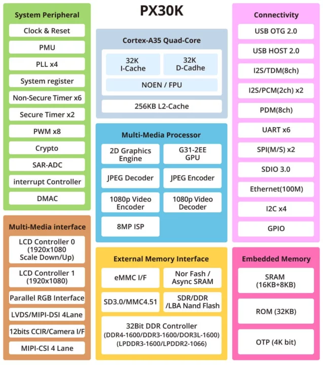
The brain of the DSOM-020R PX30 development board is the SOM DSOM-020 PX30 powered by a Rockchip PX30K low-power quad-core Arm Cortex-A35 processor designed for 24-7 operation. The processor offers plenty of GPIOs, four I2C, six UART, I2S, and camera interfaces among others. Dusun IoT integrated the PX30K into the SOM DSOM-020 PX30 module along with RAM and EMMC flash to use the board design of the customers.
The Rockchip PX30K is a variant of the better-known Rockchip PX30 processor designed to work in a wider -20 to +85°C temperature range.
DSOM-020 PX30 SOM specifications
- SoC – Rockchip PX30K quad-core Arm Cortex-A35 at up to 1.3 GHz with dual-core Mail-G31-2EE GPU with support for OpenGL ES 1.1/2.0/3.2, DirectX 11 FL9_3, OpenCL 2.0, and Vulkan 1.0.
- System Memory- Up to 2GB RAM
- Storage – Up to 128GB eMMC flash
- 144x through pads and castellated holes with
- Storage – SDIO for SD card
- Display – MIPI, LVDS, RGB Interfaces; capacitive touchscreen via USB, or resistive touchscreen via serial
- Camera – 1x MIPI CSI camera input interface or parallel camera input interface
- Audio – AC97 codec, 8-channel I2S for recording and playback of audio
- Networking – 10/100M Ethernet (on carrier PHY required)
- USB – 2x USB 2.0, including one OTG
- Low-speed I/Os – GPIOS, 6x serial, 8x PWM, 4x I2C, 2x SPI
- Analog – 3x ADC
- Power Supply – RK809 PMU with support for sleep and wake-up
- Dimensions – 45 x 45mm
- Temperature Range – Operating: -20°C to +85°C; storage: -40°C to + 85°C
- RoHS certified
- Design for 24/7 operation
Carrier board specifications
Let’s now have a closer look at the carrier board’s features.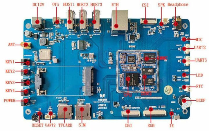
Specifications:
- Storafge – MicroSD card slot
- Display – MIPI DSI and LVDS connectors for RGB displays
- Camera – MIPI CSI connector
- Audio – Built-in microphone, 3.5mm headphone jack, speakers connector
- Networking
- 10/100M Ethernet RJ45 port
- Optional WiFi+Bluetooth or 3G/4G cellular connectivity via mini PCIe socket, SIM card slot, and SMA antenna connector
- USB – 3x USB host ports, 1x micro USB OTG port to flash the OS
- Serial – 3x UART connectors
- Misc
- IR receiver
- Buzzer
- Battery connector for RTC
- 4x user LEDs
- Power button, Reset button, 4x user-programmable buttons
- Power Supply – 12V DC power barrel jack
Installing Ubuntu to DSOM-020R PX30 development board
We’ll try installing the Ubuntu 16.04 image (the filename “DSOM-020R_img-debian_AV1.0.0.img” includes “debian” but that’s an Ubuntu image…) for PX30K provided by Dusun IoT using the RKDevTool V2.93 program in Windows since it is the recommended method. The Rockchip PX30K can be put into flash mode by pressing and holding the K1/Recovery button and then pressing the Reset button. Shortly after that, the program will detect the board and display the message “Found One LOADER Device”. We can now click on the “Upgrade Firmware” tab, select the OS image, and click on the “Upgrade” button.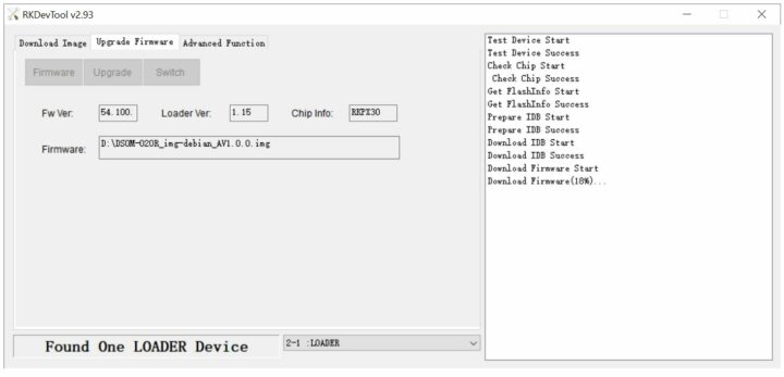
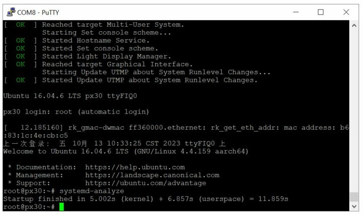
After the installation is complete, we can connect the UART2 connector on the board to the provided USB-to-Serial debug board and set the baudrate to 115200 to access the serial console. The board takes only 11 seconds to boot up to the console.
The board does not have a standard video output interface like HDMI, so the serial interface is the only option here unless the kit also includes an LCD display attached to the MIPI DSI or LVDS connector.
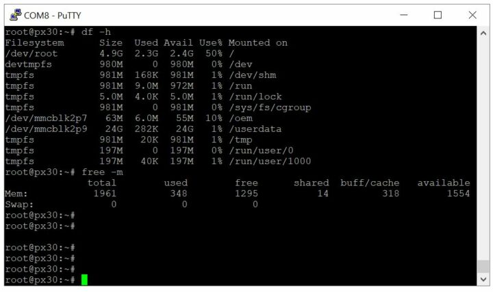
Let’s now quickly check we got a module with 2GB RAM and 32GB eMMC flash promised. The /dev/root is 4.9GB and /dev/mmcblk2p9 – which is /userdata – has a size of 24GB, so everything is fine storage-wise. If you want to install any additional programs, you have to go to /userdata and make a symbolic link pointing to it. The “free” command confirms we have 2GB of RAM.
DSOM-020R PX30 development board review with Ubuntu 16.04
We will now perform some basic functional testing to check the module information, check the eMMC flash performance, and Ethernet speed, and since we have a headless system use the board as a Zigbee gateway for IoT applications.
System benchmarks
We’ll start the benchmarks in Ubuntu with sbc-bench.sh. The script reports 1.9GB of RAM and a 4-core Rockchip PX30 CPU clocked at 1.248 GHz.
|
1 2 3 4 5 6 7 8 9 10 11 12 13 14 15 16 17 18 19 20 21 22 23 24 25 26 27 28 29 30 31 32 33 34 35 36 37 38 39 40 41 42 43 44 |
########################################################################## Linux 4.4.159 (px30) 10/13/23 _aarch64_ (4 CPU) avg-cpu: %user %nice %system %iowait %steal %idle 35.96 0.04 2.29 0.16 0.00 61.56 Device: tps kB_read/s kB_wrtn/s kB_read kB_wrtn mmcblk2 25.48 1101.17 118.88 1644479 177534 mmcblk2rpmb 0.05 0.21 0.00 312 0 total used free shared buff/cache available Mem: 1.9G 337M 1.4G 14M 229M 1.5G Swap: 0B 0B 0B CPU sysfs topology (clusters, cpufreq members, clockspeeds) cpufreq min max CPU cluster policy speed speed core type 0 0 0 408 1248 Cortex-A35 / r0p2 1 0 0 408 1248 Cortex-A35 / r0p2 2 0 0 408 1248 Cortex-A35 / r0p2 3 0 0 408 1248 Cortex-A35 / r0p2 Architecture: aarch64 Byte Order: Little Endian CPU(s): 4 On-line CPU(s) list: 0-3 Thread(s) per core: 1 Core(s) per socket: 4 Socket(s): 1 CPU max MHz: 1248.0000 CPU min MHz: 408.0000 Hypervisor vendor: horizontal Virtualization type: full SoC guess: Rockchip PX30/PX30S DT compat: rockchip,x30 rockchip,px30 Compiler: /usr/bin/gcc (Ubuntu/Linaro 5.4.0-6ubuntu1~16.04.11) 5.4.0 20160609 / aarch64-linux-gnu Userland: arm64 Kernel: 4.4.159/aarch64 cpu cpu0: leakage=11 ########################################################################## |
Under heavy load, the CPU temperature rose to 68.1 °C without any cooling heatsink or fan, and the system was still stable with no throttling detected by the script.
|
1 2 3 4 5 6 7 8 9 10 11 12 |
########################################################################## Testing maximum cpufreq again, still under full load. System health now: Time CPU load %cpu %sys %usr %nice %io %irq Temp 14:18:54: 1248MHz 3.70 91% 1% 89% 0% 0% 0% 68.1°C Checking cpufreq OPP (Cortex-A35): Cpufreq OPP: 1248 Measured: 1232 (1233.309/1232.131/1232.083) (-1.3%) ########################################################################## |
The CPU temperature ranges from 58°C to 68.8°C during the test.
|
1 2 3 4 5 6 7 8 9 10 11 12 13 14 15 16 17 18 |
System health while running 7-zip multi core benchmark: Time CPU load %cpu %sys %usr %nice %io %irq Temp 14:11:42: 1248MHz 1.08 16% 2% 13% 0% 0% 0% 58.6°C 14:12:19: 1248MHz 2.16 87% 1% 86% 0% 0% 0% 65.0°C 14:12:49: 1248MHz 3.08 86% 1% 84% 0% 0% 0% 63.8°C 14:13:19: 1248MHz 3.40 81% 1% 80% 0% 0% 0% 65.0°C 14:13:50: 1248MHz 4.04 91% 2% 89% 0% 0% 0% 66.5°C 14:14:20: 1248MHz 3.98 92% 1% 91% 0% 0% 0% 62.9°C 14:14:51: 1248MHz 3.99 90% 1% 89% 0% 0% 0% 69.2°C 14:15:21: 1248MHz 3.96 84% 2% 82% 0% 0% 0% 64.6°C 14:15:51: 1248MHz 3.63 81% 1% 80% 0% 0% 0% 65.8°C 14:16:22: 1248MHz 3.76 91% 2% 89% 0% 0% 0% 67.3°C 14:16:52: 1248MHz 3.97 92% 1% 91% 0% 0% 0% 64.2°C 14:17:23: 1248MHz 3.85 90% 1% 89% 0% 0% 0% 68.8°C 14:17:53: 1248MHz 3.70 84% 2% 82% 0% 0% 0% 66.5°C 14:18:23: 1248MHz 3.55 81% 1% 79% 0% 0% 0% 66.2°C 14:18:54: 1248MHz 3.70 91% 1% 89% 0% 0% 0% 68.1°C |
You’ll find the complete sbc-bench.sh test results at http://ix.io/4IT1.
We then tested flash storage faster with iozone using the -i parameter to read data directly from the disk without relying on the cache that may skew results:
|
1 2 3 4 5 6 7 8 9 10 11 12 13 14 15 16 |
Include fsync in write timing O_DIRECT feature enabled Auto Mode File size set to 524288 kB Record Size 1024 kB Record Size 16384 kB Command line used: iozone -e -I -a -s 512M -r 1024k -r 16384k -i 0 -i 1 -i 2 Output is in kBytes/sec Time Resolution = 0.000001 seconds. Processor cache size set to 1024 kBytes. Processor cache line size set to 32 bytes. File stride size set to 17 * record size. random random bkwd record stride kB reclen write rewrite read reread read write read rewrite read fwrite frewrite fread freread 524288 1024 99900 100142 118809 118599 117697 99016 524288 16384 108446 108354 128718 129068 128398 108575 |
The read speed is approximately 128 MB/s and the write speed is 108 MB/s, which is considered very good. For reference, the flash chip is a Samsung KLMBG2JETD-B041 eMMC 5.1 flash.
Networking performance
We tested the 10/100M Ethernet performance with iperf3 program using the router provided by AIS (broadband operator in Thailand) and found a speed of 94.2 Mbits per second, a normal result for a 100 Mbps interface.
|
1 2 3 4 5 6 7 8 9 10 11 12 13 14 15 16 17 18 19 20 |
root@px30:~/phoronix-test-suite# iperf3 -c 192.168.1.162 -f m Connecting to host 192.168.1.162, port 5201 [ 4] local 192.168.1.170 port 48940 connected to 192.168.1.162 port 5201 [ ID] Interval Transfer Bandwidth Retr Cwnd [ 4] 0.00-1.00 sec 11.6 MBytes 97.1 Mbits/sec 0 130 KBytes [ 4] 1.00-2.00 sec 11.2 MBytes 93.8 Mbits/sec 0 130 KBytes [ 4] 2.00-3.00 sec 11.2 MBytes 93.8 Mbits/sec 0 130 KBytes [ 4] 3.00-4.00 sec 11.4 MBytes 95.4 Mbits/sec 0 132 KBytes [ 4] 4.00-5.00 sec 11.2 MBytes 93.9 Mbits/sec 0 132 KBytes [ 4] 5.00-6.00 sec 11.2 MBytes 93.8 Mbits/sec 0 132 KBytes [ 4] 6.00-7.00 sec 11.2 MBytes 93.8 Mbits/sec 0 132 KBytes [ 4] 7.00-8.00 sec 11.2 MBytes 93.8 Mbits/sec 0 132 KBytes [ 4] 8.00-9.00 sec 11.4 MBytes 95.4 Mbits/sec 0 132 KBytes [ 4] 9.00-10.00 sec 11.2 MBytes 93.8 Mbits/sec 0 132 KBytes - - - - - - - - - - - - - - - - - - - - - - - - - [ ID] Interval Transfer Bandwidth Retr [ 4] 0.00-10.00 sec 113 MBytes 94.5 Mbits/sec 0 sender [ 4] 0.00-10.00 sec 112 MBytes 94.2 Mbits/sec receiver iperf Done. |
Features testing
ADC keys
The DSOM-020R PX30 development board comes with four user-programmable buttons (K1, K2, K3 and K4) that are connected to the Rockchip PX30’s ADC2 interface using different resistors values so that when a button is pressed we can read different voltage values and know which button was pressed.
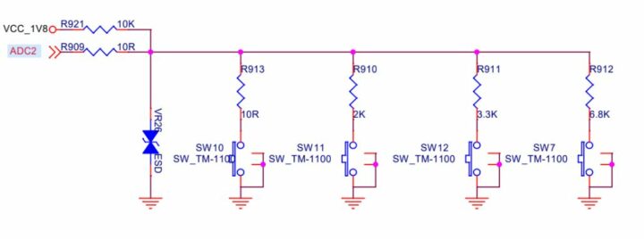 We used the sample code below for testing:
|
1 2 3 4 5 6 7 8 9 10 11 12 13 14 15 16 17 18 19 20 21 22 23 24 25 26 27 28 29 30 31 32 33 34 35 36 37 38 39 40 41 42 43 44 |
#include <unistd.h> #include <stdio.h> #include <linux/input.h> #include <stdlib.h> #include <sys/types.h> #include <sys/stat.h> #include <fcntl.h> #include <pthread.h> #define DEV_PATH "/dev/input/by-path/platform-adc-keys-event" void * thread_func(void *arg) { long now = time(NULL); while (1) { if (time(NULL) - now > 8) { exit(-2); } } } int main() { int keys_fd; char ret[2]; struct input_event t; keys_fd=open(DEV_PATH, O_RDONLY); if(keys_fd <= 0) { printf("open /dev/input/event2 device error!\n"); return -1; } printf("Please press this button within eight seconds\n"); pthread_t pid; pthread_create(&pid, NULL, thread_func, NULL); while(1) { if(read(keys_fd, &t, sizeof(t)) == sizeof(t)) { if(t.type==EV_KEY) if(t.value==0 || t.value==1) { printf("key %d %s\n", t.code, (t.value)? "Pressed" : "Released"); if(t.code == KEY_ESC) { } } } } close(keys_fd); return 0; } |
After compiling the program with gcc we successfully ran the sample to test key presses:
|
1 2 3 4 5 6 7 8 9 10 11 12 13 14 15 16 |
root@px30:/userdata# gcc key.c -o key -lpthread root@px30:/userdata# ./key Please press this button within eight seconds key 115 Pressed key 115 Released key 102 Pressed key 102 Released key 102 Pressed key 102 Released key 102 Pressed key 102 Released key 139 Pressed key 139 Released key 1 Pressed key 1 Released root@px30:/userdata# |
Using DSOM-020R PX32 development board as a Zigbee gateway
We tested the stability of the DSOM-020R PX30 development board by configuring it as a Zigbee gateway by connecting the SONOFF Zigbee 3.0 USB Dongle Plus to one of the board’s USB ports and the system detected it properly:
|
1 2 3 4 5 6 7 8 9 10 |
[14524.029940] usb 2-1.4: New USB device found, idVendor=10c4, idProduct=ea60 [14524.029985] usb 2-1.4: New USB device strings: Mfr=1, Product=2, SerialNumber=3 [14524.030014] usb 2-1.4: Product: Sonoff Zigbee 3.0 USB Dongle Plus [14524.030041] usb 2-1.4: Manufacturer: ITead [14524.030068] usb 2-1.4: SerialNumber: 7cac5da1d5c9eb118a7a8f4f1d69213e [14524.034239] bus: 'usb': really_probe: probing driver usb with device 2-1.4 [14524.036195] bus: 'usb': really_probe: probing driver cp210x with device 2-1.4:1.0 [14524.036427] cp210x 2-1.4:1.0: cp210x converter detected [14524.040038] bus: 'usb-serial': really_probe: probing driver cp210x with device ttyUSB0 [14524.041569] usb 2-1.4: cp210x converter now attached to ttyUSB0 |
We then installed Node.js – required by Zigbee2MQTT – by following the relevant instructions on GitHub.
|
1 2 3 4 5 6 7 8 9 10 11 12 13 14 15 16 17 18 19 20 21 |
root@px30:/home/9tripod# sudo apt-get install nodejs -y Reading package lists... Done Building dependency tree Reading state information... Done The following NEW packages will be installed: nodejs 0 upgraded, 1 newly installed, 0 to remove and 313 not upgraded. Need to get 27.2 MB of archives. After this operation, 128 MB of additional disk space will be used. Get:1 https://deb.nodesource.com/node_16.x nodistro/main arm64 nodejs arm64 16.2 0.2-1nodesource1 [27.2 MB] Fetched 27.2 MB in 6s (3923 kB/s) Selecting previously unselected package nodejs. (Reading database ... 113574 files and directories currently installed.) Preparing to unpack .../nodejs_16.20.2-1nodesource1_arm64.deb ... Unpacking nodejs (16.20.2-1nodesource1) ... Processing triggers for man-db (2.7.5-1) ... Setting up nodejs (16.20.2-1nodesource1) ... root@px30:/home/9tripod# node --version v16.20.2 root@px30:/home/9tripod# npm --version 8.19.4 |
The next step is to install the Zigbee2MQTT file from GitHub:
|
1 2 3 4 5 6 7 8 9 10 11 12 13 |
# Create a directory for zigbee2mqtt and set your user as owner of it sudo mkdir /opt/zigbee2mqtt sudo chown -R ${USER}: /opt/zigbee2mqtt # Clone Zigbee2MQTT repository git clone --depth 1 https://github.com/Koenkk/zigbee2mqtt.git /opt/zigbee2mqtt # Install dependencies (as user "pi") cd /opt/zigbee2mqtt npm ci # Build the app npm run build |
After the installation was complete, we started Zigbee2MQTT and this worked without any issues:
|
1 2 3 4 5 6 7 8 9 10 11 12 13 14 15 16 17 |
root@px30:/opt/zigbee2mqtt# npm start > zigbee2mqtt@1.33.1 start > node index.js Zigbee2MQTT:info 2023-10-13 20:56:15: Logging to console and directory: '/opt/z igbee2mqtt/data/log/2023-10-13.20-56-15' filename: log.txt Zigbee2MQTT:info 2023-10-13 20:56:16: Starting Zigbee2MQTT version 1.33.1 (comm it #7e63039) Zigbee2MQTT:info 2023-10-13 20:56:16: Starting zigbee-herdsman (0.19.0) Zigbee2MQTT:info 2023-10-13 20:56:42: zigbee-herdsman started (reset) Zigbee2MQTT:info 2023-10-13 20:56:42: Coordinator firmware version: '{"meta":{" maintrel":1,"majorrel":2,"minorrel":7,"product":1,"revision":20211217,"transport rev":2},"type":"zStack3x0"}' Zigbee2MQTT:info 2023-10-13 20:56:43: Currently 0 devices are joined: Zigbee2MQTT:info 2023-10-13 20:56:43: Zigbee: disabling joining new devices. Zigbee2MQTT:info 2023-10-13 20:56:43: Connecting to MQTT server at mqtt://broke r.mqttdashboard.com Zigbee2MQTT:info 2023-10-13 20:56:44: Connected to MQTT server Zigbee2MQTT:info 2023-10-13 20:56:44: MQTT publish: topic 'zigbee2mqtt/bridge/s tate', payload '{"state":"online"}' Zigbee2MQTT:info 2023-10-13 20:56:44: Started frontend on port 0.0.0.0:8080 Zigbee2MQTT:info 2023-10-13 20:56:44: Zigbee2MQTT started! |
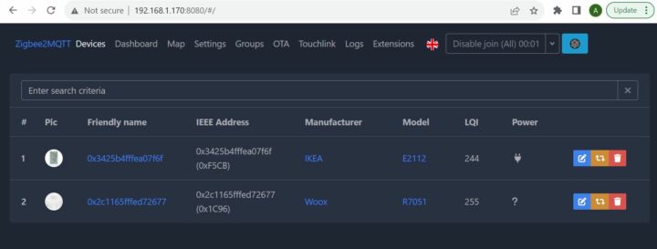
At this point, we can open the Zigbee2MQTT dashboard by typing IP address of the board with port 8080 (e.g. http://192.168.1.170:8080) in a web browser. Zigbee2MQTT will then immediately detect Zigbee devices that are in pairing mode.
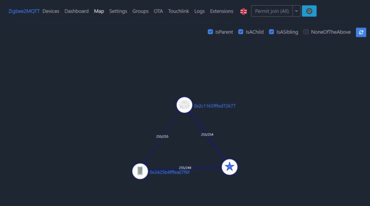
Clicking on the “Map” tab reveals that both Zigbee devices are connected directly to the DSOM-020R PX30 development board.
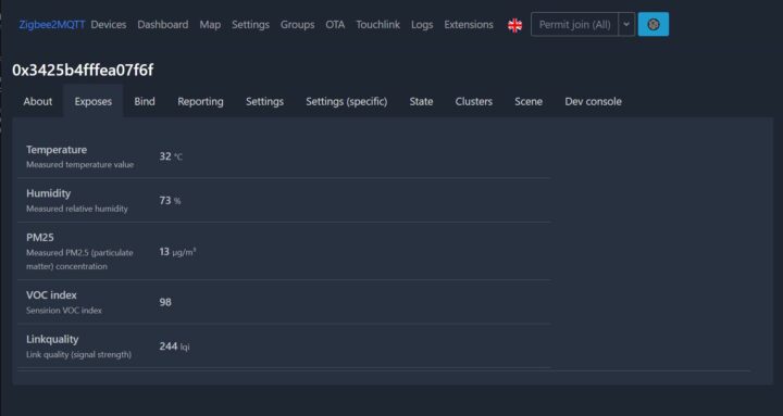
Let’s now click on the “Devices” tab, select the IKEA VINDSTYRKA air quality sensor, and click on the “Exposes” tab to check the temperature, humidity, PM2.5, and VOC index values. Everything works as expected. Great!
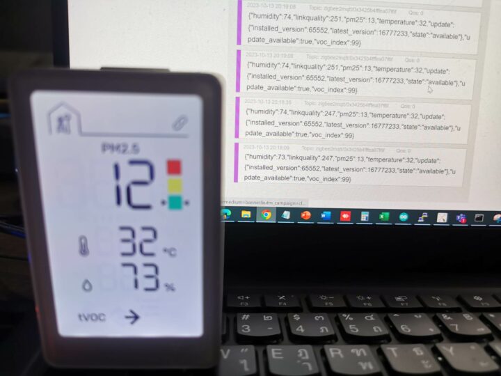
Finally, we opened an MQTT client to confirm Zigbee2MQTT was properly forwarding the values to the MQTT broker and again, that worked fine with the data updated continuously every 10 seconds.
Power consumption
Since the Rockchip PX30 is a low-power processor we measured the power consumption of the board with a multimeter.
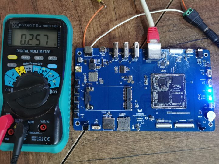
Results at 12V DC:
- Power off – 24 mA, or 288 mW
- Idle – 110mA, or 1.32 Watts
- SBC bench (7-zip multi-thread) – 257mA, or 3.088 Watts
Conclusion
After testing the DSOM-020R PX30 development board for about one month, we can conclude that the overall system is very stable and operates at low power at just 3W under load in our measurements, while the datasheet for the DSOM-020 PX30 system-on-module states that the module itself consumes up to 7.5W at most. The 12V/2A adapter delivers enough for the board and multiple peripherals attached to it.
The development kit is especially suitable for edge computing applications where low power consumption and low heat emissions are required bearing in mind the performance limitations of a quad-core Cortex-A35 processor.
Publicly available documentation for the DSOM-020R PX30 Development Board is rather limited because Dusun IoT mostly provides support via an online community where FAEs help answer various questions and support requests that users may have. This is fine for professional users developing commercial products, but this may still be frustrating to some. The good news is that Dusun IoT is working on replacing its Google Docs-based documentation with a proper online wiki and GitHub account that should have more details. We’ll provide a link to the new development resources once available.
We’d like to thank Dusun IoT Company for sending the DSOM-020R PX30 development board for review. Readers interested in the development kit can find more details on the product page and request a kit if needed (pricing is not available online at this time).
CNXSoft: This article is a translation of the review on CNX Software Thailand by Arnon Thongtem and edited by Suthinee Kerdkaew.

Jean-Luc started CNX Software in 2010 as a part-time endeavor, before quitting his job as a software engineering manager, and starting to write daily news, and reviews full time later in 2011.
Support CNX Software! Donate via cryptocurrencies, become a Patron on Patreon, or purchase goods on Amazon or Aliexpress


