There are plenty of small ESP32-C3 IoT boards with a USB-C connector on the market, and while they all look very similar, antenna designs differ, and less thought-out ones may severely impact the WiFi and Bluetooth range.
Peter Neufeld decided to hack one of those cheap ESP32-C3 boards by adding a custom antenna, and this resulted in the board having more than twice the range and almost three times in some cases.
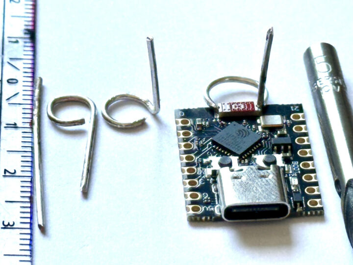
Those tiny boards are cramped, so there’s very little space around the ceramic antenna typically used, leading to poor RF performance. To work around that issue, Peter added a 31mm long antenna made of silver-plated wire, making a loop of about 8mm in diameter outside of the board and soldered on the ceramic antenna’s solder joints, and the rest of the wire (about 15mm) points upwards. As you can see from the photo above, he didn’t remove the ceramic antenna.
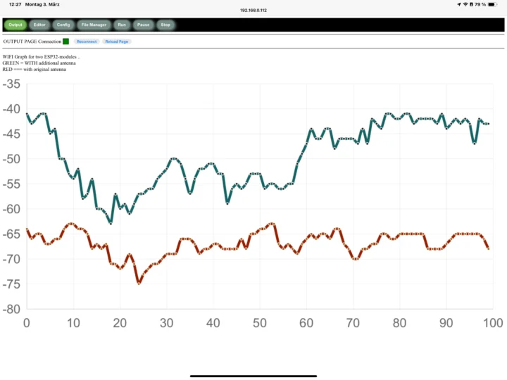
So what are the results? Not bad… 6 to 10+ dB improvements based on measurements using Peter’s custom RSSI logger written for ANNEX32 BASIC, a version of the BASIC programming language designed to run on ESP32 microcontrollers. You’ll find the code at the end of the blog post detailing the antenna hack. We can see the signal strength (RSSI) comparison of two ESP32 modules: one unmodified and one with the new antenna in the chart below.

He further explains that theoretically, every 6 dB increase in signal strength corresponds to a doubling of the range, and practical testing revealed the modified ESP32-C3 SuperMini module was able to establish a reliable WiFi connection in areas where the unmodified module could not, or was unstable.
Circuit Helper tried Peter’s antenna hack on his own ESP32-C3 boards and managed to triple the range. He reported his experiments in the video embedded below.
As a side note, Peter also provides feedback on the video above, which Circuit Helper added to the video description:
Firstly the antenna he described is shorter than the one shown in the video, the total length is 31 mm including the loop. In the video the antenna is ~30 mm with the loop adding an additional ~15 mm. I’ve compared the RSSI of both designs and found that the shorter antenna is slightly less efficient (which is an interesting finding in itself), but the gains made using the longer wire might have undesirable side effects in terms of radiation pattern etc. Another great point from Peter was in regards to the matching between the ESP C3 and chip antenna, it’s bad… there is so much reflected power that it causes overheating in the ESP, so reducing the Tx power in software can actually increase the performance, which is counterintuitive but tally’s with what some people have noted in the comments! Very interesting information and thanks again to Peter for the original design and great insight!
Via Hackaday.

Jean-Luc started CNX Software in 2010 as a part-time endeavor, before quitting his job as a software engineering manager, and starting to write daily news, and reviews full time later in 2011.
Support CNX Software! Donate via cryptocurrencies, become a Patron on Patreon, or purchase goods on Amazon or Aliexpress


Will this also work on ESP32-S3 boards of that size? They also have the same tiny ceramic antenna …
This particular board was designed by monkeys. The antenna was meant to have clearance around it but they could not read the spec sheet or daddy monkey said squash it up anyway. The boards with these antennas are mostly designed to spec so this should not be a problem.
(ps i had these boards, they were so frustrating I chucked them in the bin and got Xiaos)
What a surprise. A bigger Antenna is better.
Just solder a RP-SMA connector instead of the smd-antenna and connect your 16dbi self build Yagi antenna. I am sure it would have even further range. Physics. What a surprise that its working as known.
Of course remember to abide by EIRP limits in your region.
So, because it’s just physics, you don’t wear glasses but use binoculars instead?
I understand.
So, because it’s just physics, you don’t wear glasses but want to use binoculars instead?
Hacking is digital. This more of a modification. But great if it works and maybe the manufacturers might take note and improve quality before it goes out the door.
Nice performance improvement from this additional antenna.
… a 6 to 10 dBm improvement …
Thats totally incorrect, -65 dBm + 10 dBm ≃ 10 dBm. The improvement is ~10 dB, as -65 dBm + 10 dB = -55 dBm.
dB is a logarithmic scale, and you have to use it correctly. When you compare absolute values (e.g. -65 dBm and -55 dBm in this case), the difference on the dBm scale is a value in dB.
Adding/subtracting a “dB value” is actually multiplication. Adding 10 dB is a multiplication by 10, adding 20 dB is a multiplication by 10 * 10 = 100.
Sorry about that. My bad. I’ve fixed the article.
The original blog post reads “dB”; the plagiarists call it “dBm.” Whom do you trust?
Reflected power usually measured with SWR is mostly caused by a mismatch antenna length vs wave length. For best performance the antenna needs to match certain increments of the wave length. Longer or shorter will cause an increased SWR and can even burn out the transmitter. Ham radio deals with this a lot but it is true with ANY radio system. The shape of the antenna and ground plane matters but the length is crucial.
Anyone who has taken an ARRL course knows how to make an antenna. This isn’t a hack
I wrote a second comment down here but its still missing for days. Why is it missing?