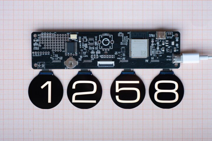
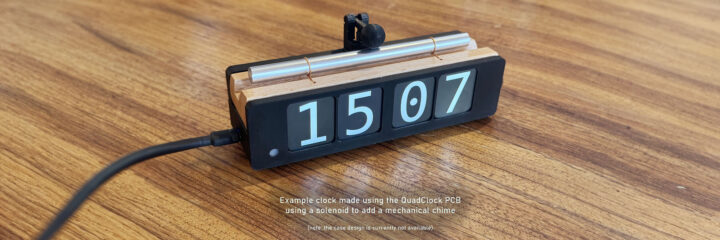
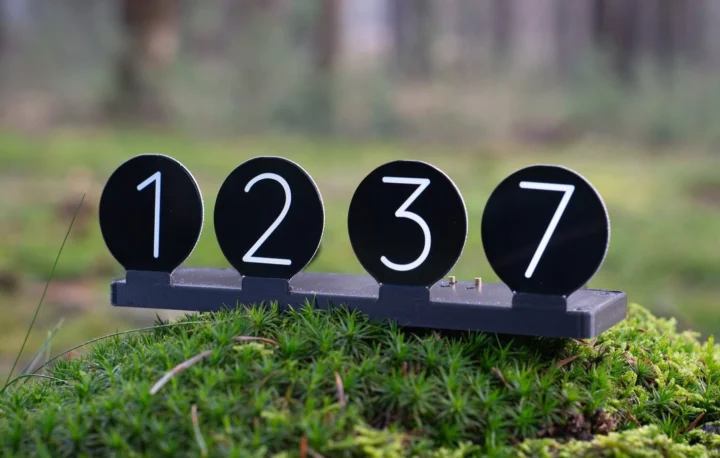
The QuadClock PCB is an ESP32-S3-powered multi-display clock controller designed to serve as a foundation for creating a four-TFT-display clock. It supports up to four 1.69-inch rectangular TFT displays (240×280) or four 1.28” round displays (240×240). It manages essential functions such as driving the displays and maintaining precise time, allowing you to focus on crafting a unique enclosure or integrating additional features.
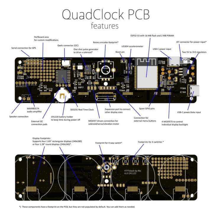
It is open-source and is powered by the ESP32-WROOM-1 module with up to 16MB flash and 2MB PSRAM. It supports independent brightness control for each mounted display via four MOSFETs and includes an onboard real-time clock with a backup battery for accurate timekeeping.
The QuadClock PCB is designed for enthusiasts and makers interested in creating multi-display clock projects. It can also be used for stock tickers, weather displays, and smart home dashboards.
We previously covered the 2×2 Quad Display board with either Raspberry Pi Pico W or ESP32-S3-WROOM-1 module to drive four displays, but the QuadClock PCB offers a different layout.
QuadClock PCB specifications:
- Wireless module – ESP32-S3-WROOM-1 module
- SoC – ESP32-S3, dual-core 32-bit microcontroller @ 240MHz
- Storage – 2MB PSRAM (Note: however the schematics show ESP32-S3-WROOM-1 (N16R8) implying 8MB PSRAM)
- Memory – 16MB flash
- Wireless – 2.4GHz Wi-Fi and Bluetooth 5 (LE)
- Display – 4x 1.69” rectangular TFT displays (240×280) or 4x 1.28” round displays (240×240)
- Audio – MAX98357AEWL+T Audio Amplifier (3W output for clock alarms or sound effects)
- USB – 2x USB-C (one for power and firmware updates, one for power only)
- Expansion
- Qwiic I2C connector
- Flat cable expansion connector (SPI, I2C, power, and control signals for alternative displays or custom modules)
- GPS module header for precision time synchronization
- Misc – Rotary encoder, 4x button switches, 5-way switch, real-time clock, accelerometer, one-shot trigger circuit (optional, not populated by default), servo header (3-pin), 4x MOSFETs (for backlight control)
- Power supply
- 5V via USB-C
- 3.3V regulator
- Dimensions – TBD
The QuadClock ESP32-based clock controller is declared as “not entirely beginner-friendly” as it requires precise soldering to mount the TFT displays if not ordered pre-mounted. The documentation page lists hardware design files and includes instructions for mounting the displays and installing firmware. The C++ source code is available on GitHub.
The QuadClock PCB is priced at $39 on Tindie for the baseboard alone. Buyers can include mounted 1.28-inch and 1.69-inch displays for $34 and $30 extra, respectively. There is a discount for buying more than one unit. Alternatively, the QuadClock Orbix is a fully assembled product built around the QuadClock PCB.

Tomisin is a writer specializing in hardware product reviews, comparisons, and explainers. He is very passionate about small form factor and single-board computers.
Support CNX Software! Donate via cryptocurrencies, become a Patron on Patreon, or purchase goods on Amazon or Aliexpress


