Raspberry Pi has just launched the Compute Module 5 (CM5) and the company sent me a “Raspberry Pi Development Kit for CM5” for review and to play around with the new Broadcom BCM2712 system-on-module succeeding the Raspberry Pi Compute Module 4 (CM4) introduced in 2020.
Today, I’ll have a first look at the development kit checking out the hardware, connecting accessories, booting it up to Raspberry Pi OS, and collecting some basic system information. I’ll do a more in-depth review in a few weeks.
Unboxing of the Raspberry Pi Development Kit for CM5
I received the kit in a package reading “Raspberry Pi Development Kit” and “For Raspberry Pi CM5”. That’s a good start…
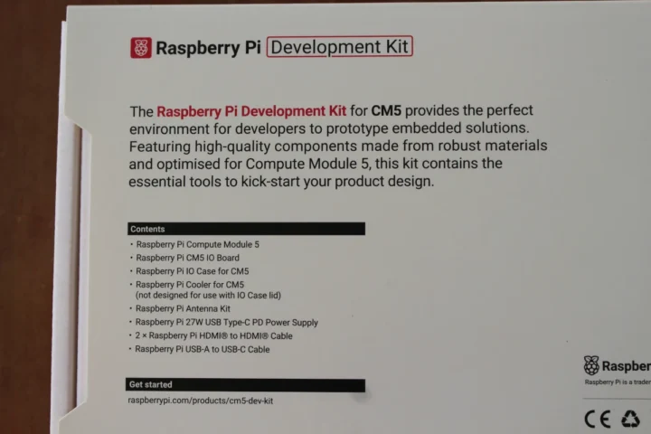
The bottom side lists the package’s content which I will check out shortly, and a link to the documentation.
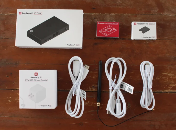
Let’s see what we have with the Raspberry Pi Development Kit: a Raspberry Pi IO Case, a Raspberry Pi Compute Module 5, a Raspberry Pi Cooler (not designed for use with the IO case lid), a 27W USB-C power adapter, two HDMI cables, a USB-A to USB-C cable, and a Raspberry Pi Antenna Kit. I can’t see the Raspberry Pi CM5 IO board, but I hope it will be inside the IO case package…
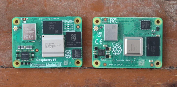
Let’s check out the Raspberry Pi CM5 first and compare it to the Raspberry Pi CM4 (Lite) since I don’t own a CM4 module.
There’s one more component on the top inside: the Raspberry Ri RP1 peripheral controller also found in the Raspberry Pi 5 SBC. The power chip is larger having replaced the Dialog DA9090 by a Renesas DA9091 PMIC with some merger and acquisition activity happening in the meantime. If we zoom in on the configuration resistors on the top right side of the CM5 module, we can see I have a CM5104032 model with 4GB RAM, 32GB flash, and a wireless module. We’ll also notice some unannounced options, so it looks like a cheaper Raspberry Pi Compute Module 5 module with 1GB RAM and 8GB eMMC flash may eventually become available, as well as higher-end ones with up to 128GB eMMC flash.
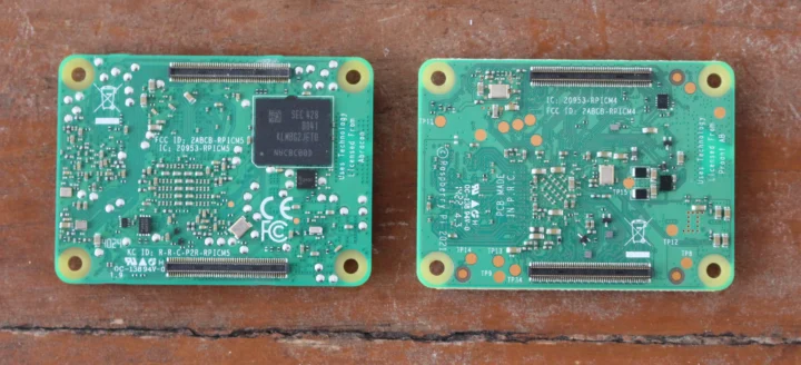
The CM4 modules have their eMMC flash placed on top, but due to the RP1 chip on the CM5, the eMMC flash had to be moved to the bottom side of the module. We still have the two board-to-board (B2B) connectors in the same position and with the same layout.
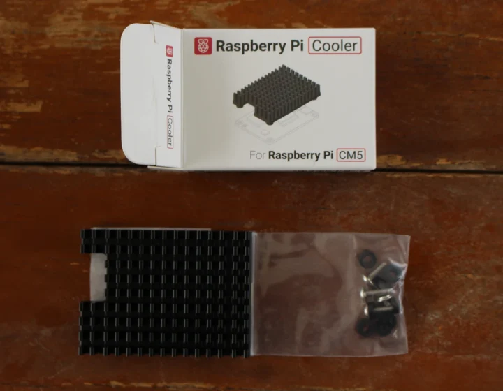
The Raspberry Pi Cooler comes with a screw set, and we can see an opening on the left for the antennas.
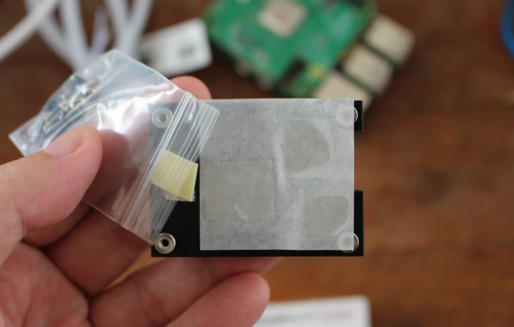
The bottom side has three thermal pads to make sure the Raspberry Pi CM5 keeps cool under heavy loads.
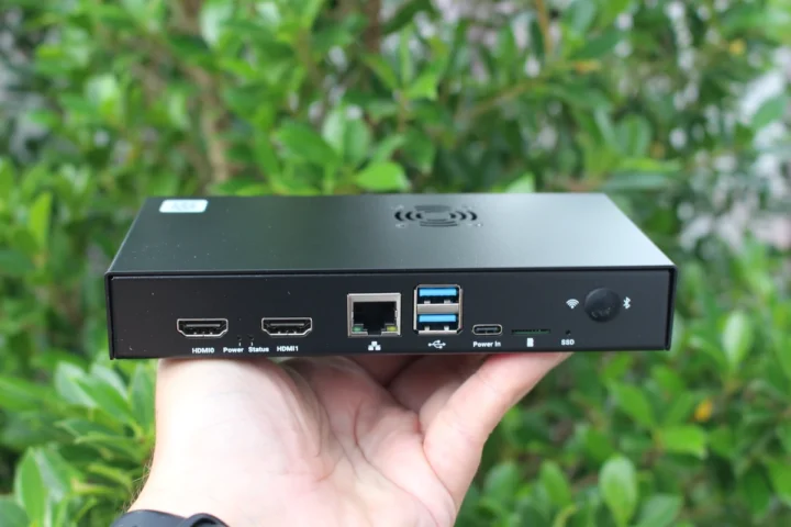
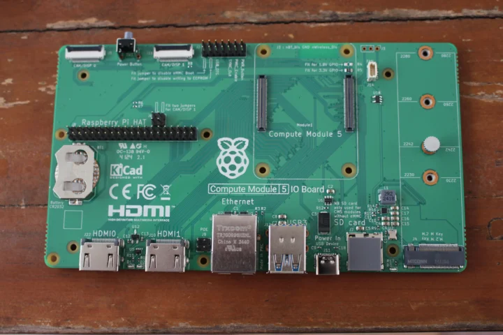
I’m glad to finally confirm my IO case did come with a Raspberry Pi CM5 IO board. More of the ports can be found on the rear panel with two HDMI ports, Power and Status LEDs, a gigabit Ethernet RJ45 jack, two USB 3.0 ports, a USB-C port for power, a microSD card for CM5 Lite only, an SSD activity LED, and an opening for the WIFi and Bluetooth antenna.
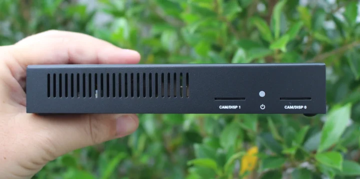
The front panel has some ventilation holes, two openings for MIPI camera/display cables, and a power button.
Raspberry Pi Development Kit assembly and hardware setup
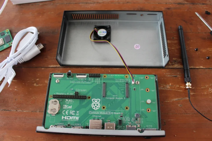
Let’s open the case by loosening the four screws (two on each side) holding the two parts together. A fan is connected to the lid for cooling. Let’s remove four more screws and disconnect the fan cable to take out the Raspberry Pi CM5 IO board.
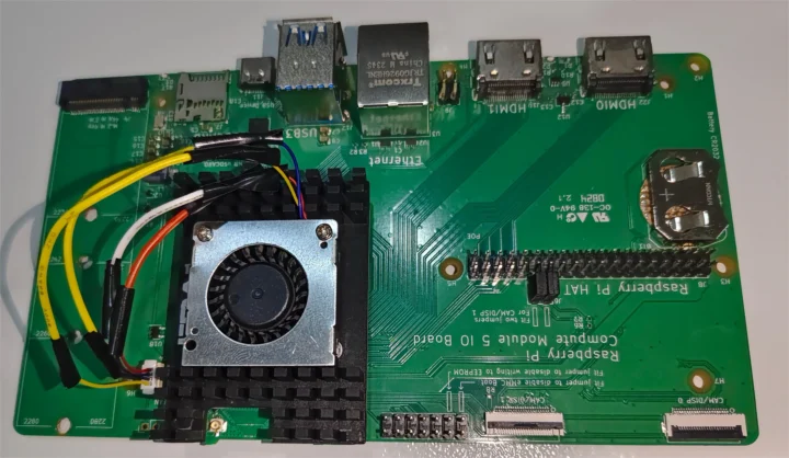
The board comes with a CR2032 battery holder for the RTC battery, a 40-pin Raspberry Pi GPIO header with mounting holes for HAT expansion boards, a 4-pin configuration header, a 4-pin PoE header, the board-to-board connectors for the CM5 module, and M.2 M-key socket for 2230, 2242, 2260, or 2280 NVMe SSD, and a 14-pin “Jumper” header to configure boot, EEPROM write-protect, USB OTG, etc… as well as connect a power push button.
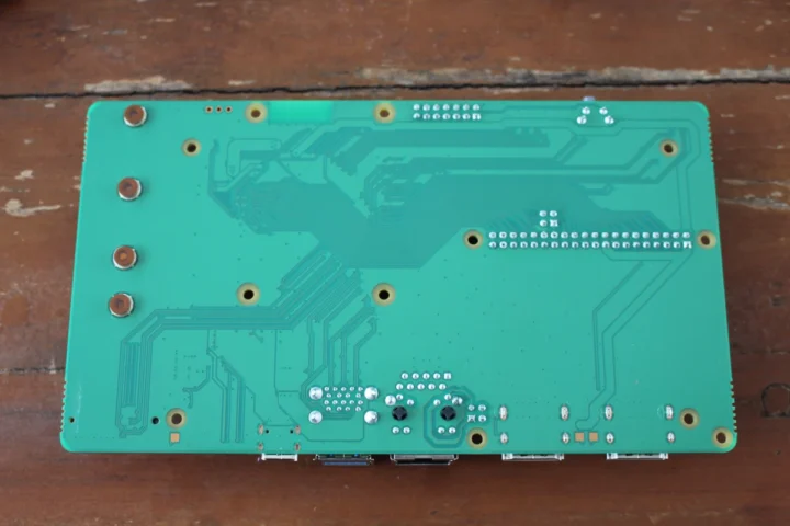
There aren’t any components on the bottom side.
Let’s now start the assembly by adding the SMA connector to the IO case.
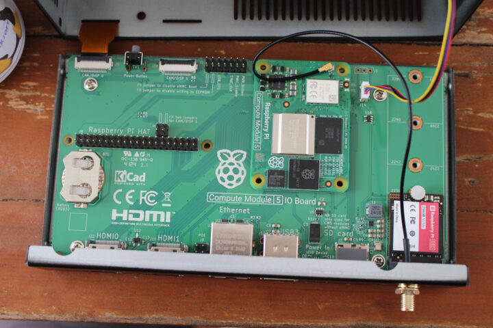
We can now put the Compute Module 5 IO board back inside the IO case, insert the Raspberry Pi CM5 module, connect the WiFi antenna to the module, and add an official 256GB Raspberry Pi NVMe SSD. Ideally, I would have added a CR2032 battery, but I don’t have any.
I also connected a Raspberry Pi Camera Module 3 to the CAM/DISP 0 connector passing the cable through the opening in the IO case. I planned to connect a Raspberry Pi Touch Display 2 too, but I skipped it for now because it requires 5V from the 40-pin Raspberry Pi header and I want to first test the Raspberry Pi Developer Kit with the IO case fully closed. However, it will work fine if we keep the IO case open since we have access to the 5V/GND on the GPIO header that way.
I did not use the Raspberry Pi cooler for the same reason, since Raspberry Pi mentions it’s not designed to be used with the IO Case lid. That means we’ll just use the PWM fan for cooling.
First boot to Raspberry Pi OS and system information
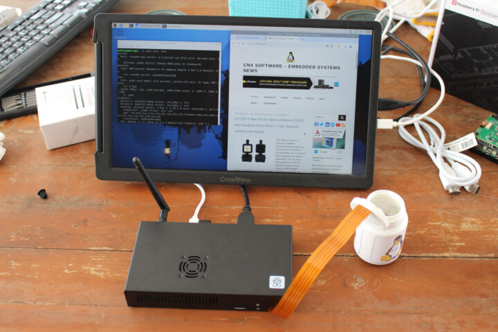
Let’s close the lid add the external WiFi antenna, and try to boot the system up after connecting an HDMI monitor and RF dongles for a keyboard and a mouse.
The system was up and running even though, I had not flashed Raspberry Pi OS to the eMMC flash. The explanation is simple: the Development Kit simply booted from the 256GB SSD preloaded with Raspberry Pi OS.
|
1 2 3 4 5 6 7 8 9 |
pi@raspberrypi:~ $ df -h Filesystem Size Used Avail Use% Mounted on udev 1.9G 0 1.9G 0% /dev tmpfs 405M 6.4M 398M 2% /run /dev/nvme0n1p2 235G 5.1G 218G 3% / tmpfs 2.0G 34M 2.0G 2% /dev/shm tmpfs 5.0M 48K 5.0M 1% /run/lock /dev/nvme0n1p1 510M 76M 435M 15% /boot/firmware tmpfs 405M 208K 404M 1% /run/user/1000 |
But inxi confirms we also have a 32GB eMMC flash (Samsung BJTD4R) and other system information:
|
1 2 3 4 5 6 7 8 9 10 11 12 13 14 15 16 17 18 19 20 21 22 23 24 25 26 27 28 29 30 31 32 33 34 35 36 37 38 39 40 41 42 43 44 45 46 47 48 |
pi@raspberrypi:~ $ sudo inxi -Fc0 System: Host: raspberrypi Kernel: 6.6.51+rpt-rpi-2712 arch: aarch64 bits: 64 Console: pty pts/2 Distro: Debian GNU/Linux 12 (bookworm) Machine: Type: ARM System: Raspberry Pi Compute Module 5 Rev 1.0 details: N/A rev: c04180 serial: 2332d973fae3ffd8 CPU: Info: quad core model: N/A variant: cortex-a76 bits: 64 type: MCP cache: L2: 2 MiB Speed (MHz): avg: 2400 min/max: 1500/2400 cores: 1: 2400 2: 2400 3: 2400 4: 2400 Graphics: Device-1: bcm2712-hdmi0 driver: vc4_hdmi v: N/A Device-2: bcm2712-hdmi1 driver: vc4_hdmi v: N/A Display: wayland server: X.org v: 1.21.1.7 with: Xwayland v: 22.1.9 compositor: LabWC driver: gpu: vc4-drm,vc4_crtc,vc4_dpi,vc4_dsi,vc4_firmware_kms,vc4_hdmi,vc4_hvs,vc4_txp,vc4_v3d,vc4_vec tty: 80x24 resolution: 1920x1080 API: EGL/GBM Message: No known Wayland EGL/GBM data sources. Audio: Device-1: bcm2712-hdmi0 driver: vc4_hdmi Device-2: bcm2712-hdmi1 driver: vc4_hdmi API: ALSA v: k6.6.51+rpt-rpi-2712 status: kernel-api Network: Device-1: Raspberry Pi RP1 PCIe 2.0 South Bridge driver: rp1 IF: wlan0 state: up mac: 2c:cf:67:b2:8d:ea IF-ID-1: eth0 state: down mac: 2c:cf:67:b2:8d:e8 Bluetooth: Device-1: bcm7271-uart driver: bcm7271_uart Report: hciconfig ID: hci0 state: up address: 2C:CF:67:B2:8D:EB bt-v: 3.0 Device-2: bcm7271-uart driver: N/A Drives: Local Storage: total: 267.6 GiB used: 5.17 GiB (1.9%) ID-1: /dev/mmcblk0 type: Removable vendor: Samsung model: BJTD4R size: 29.12 GiB ID-2: /dev/nvme0n1 vendor: Samsung model: MZ9LQ256HBJD-00BVL size: 238.47 GiB Partition: ID-1: / size: 234.2 GiB used: 5.1 GiB (2.2%) fs: ext4 dev: /dev/nvme0n1p2 Swap: ID-1: swap-1 type: file size: 200 MiB used: 0 KiB (0.0%) file: /var/swap Sensors: System Temperatures: cpu: 68.8 C mobo: N/A Fan Speeds (RPM): cpu: 3516 Info: Processes: 214 Uptime: 4h 54m Memory: 3.95 GiB used: 1.33 GiB (33.5%) gpu: 8 MiB Init: systemd target: graphical (5) Shell: Sudo inxi: 3.3.26 |
The camera is not detected, I might have to double-check the connection, and I might have set some jumpers. I’ll check that in the second part of the review:
|
1 2 |
pi@raspberrypi:~ $ rpicam-hello --list No cameras available! |
The idle temperature is a little high at 68.8°C because there’s no heatsink and we only rely on the fan. Let’s run sbc-bench.sh script to see if thermal throttling does occur:
|
1 2 3 4 5 6 7 8 9 10 11 12 13 14 15 16 17 18 19 20 21 22 23 24 25 26 27 28 29 30 31 32 33 34 35 36 37 38 39 40 41 42 43 44 45 46 47 48 49 50 51 52 53 54 55 56 57 58 59 60 61 62 63 64 65 66 67 68 69 70 71 72 73 74 75 76 77 78 79 80 81 82 83 84 85 86 87 88 89 90 91 92 93 94 95 96 97 98 99 100 101 102 103 104 105 106 107 108 109 110 111 112 113 114 115 116 117 118 119 120 121 122 123 124 125 126 127 128 129 130 131 132 133 134 135 136 137 138 139 140 141 142 143 144 |
pi@raspberrypi:~ $ sudo ./sbc-bench.sh -r Starting to examine hardware/software for review purposes... sbc-bench v0.9.68 Installing needed tools: distro packages already installed, cpuminer. Done. Checking cpufreq OPP. Done. Executing tinymembench. Done. Executing RAM latency tester. Done. Executing OpenSSL benchmark. Done. Executing 7-zip benchmark. Done. Throttling test: heating up the device, 5 more minutes to wait. Done. Checking cpufreq OPP again. Done (12 minutes elapsed). Results validation: * Measured clockspeed not lower than advertised max CPU clockspeed * No swapping * Background activity (%system) OK * Too much other background activity: 0% avg, 6% max -> https://tinyurl.com/mr2wy5uv * Throttling / frequency capping (under-voltage) occured -> https://tinyurl.com/4ky59sys / https://tinyurl.com/3j2c66kd Full results uploaded to https://0x0.st/XRKl.txt # Raspberry Pi Compute Module 5 Rev 1.0 Tested with sbc-bench v0.9.68 on Wed, 27 Nov 2024 15:17:58 +0700. Full info: [https://0x0.st/XRKl.txt](http://0x0.st/XRKl.txt) ### General information: Information courtesy of cpufetch: SoC: Broadcom BCM2712 Technology: 16nm Microarchitecture: Cortex-A76 Max Frequency: 2.400 GHz Cores: 4 cores Features: NEON,SHA1,SHA2,AES,CRC32 BCM2712, Kernel: aarch64, Userland: arm64 CPU sysfs topology (clusters, cpufreq members, clockspeeds) cpufreq min max CPU cluster policy speed speed core type 0 0 0 1500 2400 Cortex-A76 / r4p1 1 0 0 1500 2400 Cortex-A76 / r4p1 2 0 0 1500 2400 Cortex-A76 / r4p1 3 0 0 1500 2400 Cortex-A76 / r4p1 4041 KB available RAM ### Governors/policies (performance vs. idle consumption): Original governor settings: cpufreq-policy0: performance / 2400 MHz (conservative ondemand userspace powersave performance schedutil / 1500 1600 1700 1800 1900 2000 2100 2200 2300 2400) Tuned governor settings: cpufreq-policy0: performance / 2400 MHz Status of performance related policies found below /sys: /sys/module/pcie_aspm/parameters/policy: default [performance] powersave powersupersave ### Clockspeeds (idle vs. heated up): Before at 73.2°C: cpu0 (Cortex-A76): OPP: 2400, ThreadX: 2400, Measured: 2399 After at 84.8°C (throttled): cpu0 (Cortex-A76): OPP: 2400, ThreadX: 2400, Measured: 2403 ### Performance baseline * memcpy: 5304.3 MB/s, memchr: 13456.6 MB/s, memset: 11936.3 MB/s * 16M latency: 119.0 118.8 117.2 115.3 122.0 119.1 139.2 134.3 * 128M latency: 135.0 134.2 136.5 141.3 135.2 134.0 135.7 136.4 * 7-zip MIPS (3 consecutive runs): 9831, 9085, 8992 (9300 avg), single-threaded: 3191 * `aes-256-cbc 540403.95k 1003620.69k 1256036.52k 1332896.09k 1365554.52k 1367932.93k` * `aes-256-cbc 540634.79k 1003600.96k 1256047.70k 1332894.72k 1365325.14k 1368255.15k` ### PCIe and storage devices: * Raspberry RP1 PCIe 2.0 South Bridge: Speed 5GT/s, Width x4, driver in use: rp1, ASPM Disabled * 238.5GB "SAMSUNG MZ9LQ256HBJD-00BVL" SSD as /dev/nvme0: Speed 8GT/s, Width x1 (downgraded), 0% worn out, drive temp: 40°C, ASPM Disabled * 29.1GB "Samsung BJTD4R" HS400 Enhanced strobe eMMC 5.1 card as /dev/mmcblk0: date 07/2024, manfid/oemid: 0x000015/0x0100, hw/fw rev: 0x0/0x0300000000000000 ### Swap configuration: * /var/swap on /dev/nvme0n1p2: 200.0M (0K used) ### Software versions: * Debian GNU/Linux 12 (bookworm) * Build scripts: http://archive.raspberrypi.com/debian/ bookworm main * Compiler: /usr/bin/gcc (Debian 12.2.0-14) 12.2.0 / aarch64-linux-gnu * OpenSSL 3.0.15, built on 3 Sep 2024 (Library: OpenSSL 3.0.15 3 Sep 2024) * ThreadX: 26826259 / 2024/09/23 14:02:56 ### Kernel info: * `/proc/cmdline: reboot=w coherent_pool=1M 8250.nr_uarts=1 pci=pcie_bus_safe smsc95xx.macaddr=2C:CF:67:B2:8D:E8 vc_mem.mem_base=0x3fc00000 vc_mem.mem_size=0x40000000 console=ttyAMA10,115200 console=tty1 root=PARTUUID=c15065e6-02 rootfstype=ext4 fsck.repair=yes rootwait quiet splash plymouth.ignore-serial-consoles` * Vulnerability Spec store bypass: Mitigation; Speculative Store Bypass disabled via prctl * Vulnerability Spectre v1: Mitigation; __user pointer sanitization * Vulnerability Spectre v2: Mitigation; CSV2, BHB * Kernel 6.6.51+rpt-rpi-2712 / CONFIG_HZ=250 All known settings adjusted for performance. Device now ready for benchmarking. Once finished stop with [ctrl]-[c] to get info about throttling, frequency cap and too high background activity all potentially invalidating benchmark scores. All changes with storage and PCIe devices as well as suspicious dmesg contents will be reported too. Time fake/real load %cpu %sys %usr %nice %io %irq Temp VCore PMIC DC(V) 15:18:04: 2400/2400MHz 3.33 2% 0% 2% 0% 0% 0% 78.2°C 0.8948V 3.0W 5.12V 15:19:04: 2400/2400MHz 1.22 0% 0% 0% 0% 0% 0% 70.5°C 0.8948V 2.9W 5.12V Cleaning up. Done. Checking cpufreq OPP again. Done. Clockspeeds now at 73.8°C: cpu0 (Cortex-A76): OPP: 2400, ThreadX: 2400, Measured: 2399 Results validation: * Measured clockspeed not lower than advertised max CPU clockspeed * No swapping * Background activity (%system) OK * Throttling / frequency capping (under-voltage) occured -> https://tinyurl.com/4ky59sys / https://tinyurl.com/3j2c66kd Querying ThreadX on RPi for thermal or undervoltage issues: 11100000000000000000 ||| |||_ under-voltage ||| ||_ currently throttled ||| |_ arm frequency capped |||_ under-voltage has occurred since last reboot ||_ throttling has occurred since last reboot |_ arm frequency capped has occurred since last reboot |
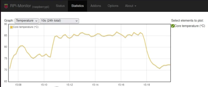
Note the devkit is placed on my terrace outdoors with a 32°C ambient temperature. Here’s the CPU temperature from rpimonitor during the benchmark.
Looking at the log, The real CPU frequency dropped as low as 1.5 GHz during 7-zip:
|
1 2 3 4 5 6 7 8 9 10 11 12 13 14 15 16 |
System health while running 7-zip multi core benchmark: Time fake/real load %cpu %sys %usr %nice %io %irq Temp VCore PMIC DC(V) 15:10:35: 2400/2400MHz 1.07 0% 0% 0% 0% 0% 0% 76.5°C 0.8945V 3.4W 5.12V 15:10:45: 2400/2256MHz 1.67 92% 0% 92% 0% 0% 0% 83.7°C 0.8948V 5.3W 5.11V 15:10:56: 2400/1500MHz 2.03 94% 0% 93% 0% 0% 0% 84.2°C 0.8958V 6.0W 5.11V 15:11:06: 2400/1500MHz 2.33 90% 0% 89% 0% 0% 0% 84.8°C 0.8953V 5.5W 5.11V 15:11:17: 2400/2201MHz 2.74 97% 0% 96% 0% 0% 0% 84.8°C 0.7489V 3.2W 5.13V 15:11:28: 2400/2201MHz 3.15 94% 0% 94% 0% 0% 0% 85.3°C 0.8950V 5.2W 5.13V 15:11:38: 2400/1500MHz 3.44 94% 0% 93% 0% 0% 0% 83.2°C 0.8961V 5.7W 5.12V 15:11:48: 2400/2146MHz 3.53 93% 0% 92% 0% 0% 0% 83.2°C 0.8932V 5.1W 5.10V 15:12:01: 2400/1500MHz 3.68 93% 1% 91% 0% 0% 0% 85.3°C 0.7497V 4.1W 5.13V 15:12:12: 2400/1500MHz 3.73 96% 0% 96% 0% 0% 0% 85.9°C 0.7497V 3.7W 5.12V 15:12:23: 2400/2146MHz 3.86 94% 0% 93% 0% 0% 0% 84.2°C 0.7505V 4.0W 5.15V 15:12:33: 2400/2256MHz 3.88 96% 0% 95% 0% 0% 0% 83.2°C 0.7497V 3.0W 5.15V 15:12:46: 2400/1500MHz 3.90 88% 1% 86% 0% 0% 0% 84.8°C 0.8948V 5.6W 5.12V |
The fan turned at full speed, but it was still not enough. I’ll repeat the test indoors, and then with the board outside the case using the official Cooler. I’ll also try to get a CM5 active cooler from EDATEC as shown below.
The company did their own test at 25°C using sysbench, and the CPU temperature topped at around 60°C with the active cooler.
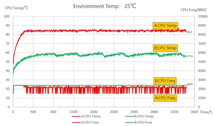
They also tested the same setup at 60°C, and the Raspberry Pi CM5 (without a heatsink) only ran for about 16 minutes before dying. With the active cooler, the temperature stabilized at 74°C under those conditions.
I’ll do more testing in the second part of the review. I’d like to thank Raspberry Pi for sending the Development Kit for CM5 for review. It can be purchased for $130 plus taxes and shipping on authorized distributors.

Jean-Luc started CNX Software in 2010 as a part-time endeavor, before quitting his job as a software engineering manager, and starting to write daily news, and reviews full time later in 2011.
Support CNX Software! Donate via cryptocurrencies, become a Patron on Patreon, or purchase goods on Amazon or Aliexpress


