The Raspberry Pi RP2350 microcontroller adds an HSTX (High-Speed Serial Transmit) interface adding the PIOs (Programmable IOs) introduced on the Raspberry Pi RP2040 three years ago. The RP2350 MCU now has three PIOs and one HSTX interface going over 8x GPIOs. So let’s try to better understand what HSTX is exactly, what it is used for, and how it differs from PIOs. We’ll also check out some programming examples in C and MicroPython.
The high-speed serial transmit (HSTX) interface is detailed in the RP2350 datasheet starting on page 1118 where it reads “The high-speed serial transmit (HSTX) interface streams data from the system clock domain to up to 8 GPIOs at a rate independent of the system clock”. Reading further, we also learn that it runs at 150 MHz enabling up to 300 Mbps per pin with DDR output operation, or a combined 2,400 Mbps over 8 pins if I understood that right…

Here’s a bit more of the description from the datasheet
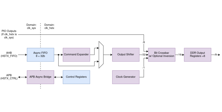
The HSTX is asynchronous from the rest of the system. A 32-bit-wide FIFO provides high-bandwidth access from the system DMA. The command expander performs simple manipulation of the datastream, and the output shift register portions the 32-bit data out over successive HSTX clock cycles, swizzled by the bit crossbar. The outputs are double-data-rate: up to two bits per pin per clock cycle.
HSTX drives data through GPIOs using DDR output registers to transfer up to two bits per clock cycle per pin. The HSTX balances all delays to GPIO outputs within 300 picoseconds, minimizing common-mode components when using neighboring GPIOs as a pseudo-differential driver. This also helps maintain destination setup and hold time when a clock is driven alongside the output data.
The maximum frequency for the HSTX clock is 150MHz, the same as the system clock. With DDR output operation, this is a maximum data rate of 300Mb/s per pin. There are no limits on the frequency ratio of the system and HSTX clocks, however, each clock must be individually fast enough to maintain your required throughput. Very low system clock frequencies coupled with very high HSTX frequencies may encounter system DMA bandwidth limitations since the DMA is capped at one HSTX FIFO write per system clock cycle.
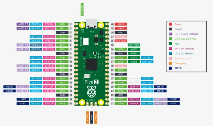
On the Raspberry Pi RP2350, GPIOs 12 through 19 are HSTX-capable. Note that HSTX is output-only, so it’s not quite as flexible as PIOs which allow users to create all sorts of high-speed (or not) interfaces. I modified the Raspberry Pi Pico 2 pinout diagram to highlight the HSTX-capable GPIOs.

What HSTX can it be used for?
HSTX is capable of high-speed transfer but can only transmit data and not receive it, so it appears especially useful for video outputs and display interfaces. However, it would not be suitable for bidirectional transfers, for instance, you could not emulate an Ethernet interface.
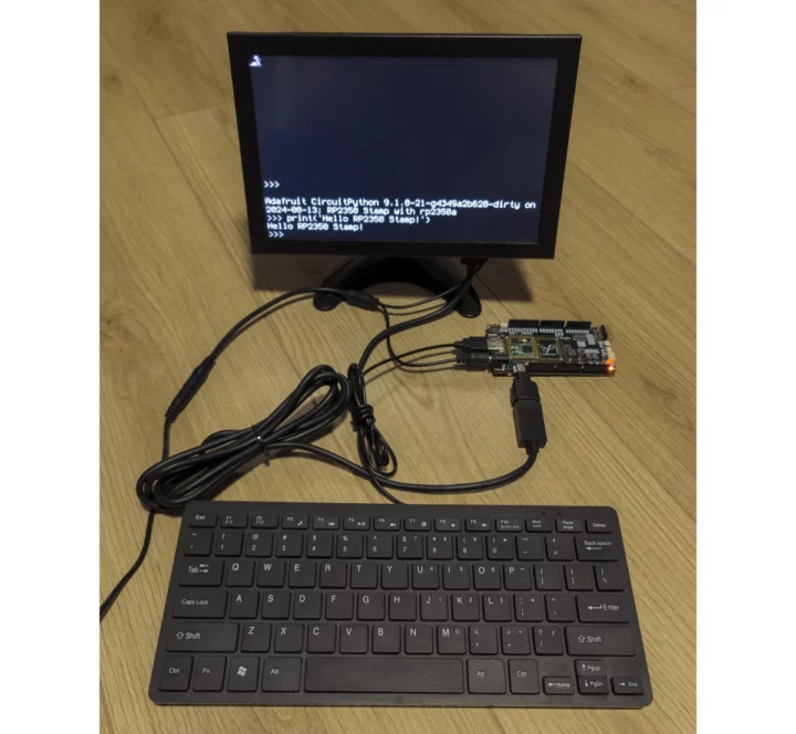
The Raspberry Pi RP2040’s PIOs were used to create DVI, VGA, and composite video outputs, but in the RP2350 board the programmable I/O blocks may be freed, and the HSTX interface used instead. While you could use the Raspberry Pi Pico 2 to play around with the HSTX interface, you’d have some soldering to do, and a more convenient way to be started is getting a board like the RP2xxx Stamp Carrier XL in combination with the R2350 Stamp module since it exposes the HSTX interface through a micro HDMI port.
The photo above shows the RP2xxx Stamp Carrier XL board connected to a keyboard and a display showing the CircuitPython REPL interface, and arturo182 confirmed it’s using HSTX on X. I could not find specific code for it yet, or maybe the default CircuitPython image already works that way [Update: yes, and the code can be found @ https://github.com/adafruit/circuitpython/blob/main/ports/raspberrypi/common-hal/picodvi/Framebuffer_RP2350.c].
More boards from Adafruit, Pimoroni, and others are coming soon with video outputs and/or displays with HSTX support.
HSTX code samples for RP2350 in C
Raspberry Pi provides two HSTX code samples in the Raspberry Pi Pico C/C++ SDK:
- dvi_out_hstx_encoder – This sample generates DVI output using the command expander and TMDS encoder in HSTX. The frame buffer resolution is set to 640×480. This example requires an external digital video connector connected to GPIOs 12 through 19 with appropriate current-limiting resistors, e.g. 270 ohms. This example can be used directly with the Pico DVI Sock board which can be soldered onto a Raspberry Pi Pico 2.
- spi_lcd – This sample drives an ST7789 SPI LCD using the HSTX. The SPI clock rate is fully independent of (and can be faster than) the system clock. It was tested at a 240×240 resolution using a WaveShare 1.3-inch ST7789 module.
Both samples are too long to be embedded into this article, so I’ll show the HSTX-related code from the SPI LCD samples:
|
1 2 3 4 5 6 7 8 9 10 11 12 13 14 15 16 17 18 19 20 21 22 23 24 25 26 27 28 29 30 31 32 33 34 35 36 |
#include "hardware/structs/hstx_ctrl.h" #include "hardware/structs/hstx_fifo.h" // These can be any permutation of HSTX-capable pins: #define PIN_DIN 12 #define PIN_SCK 13 #define PIN_CS 14 #define PIN_DC 15 // These can be any pin: #define PIN_RESET 16 #define PIN_BL 17 #define FIRST_HSTX_PIN 12 #if PIN_DIN < FIRST_HSTX_PIN || PIN_DIN >= FIRST_HSTX_PIN + 8 #error "Must be an HSTX-capable pin: DIN" #elif PIN_SCK < FIRST_HSTX_PIN || PIN_SCK >= FIRST_HSTX_PIN + 8 #error "Must be an HSTX-capable pin: SCK" #elif PIN_CS < FIRST_HSTX_PIN || PIN_CS >= FIRST_HSTX_PIN + 8 #error "Must be an HSTX-capable pin: CS" #elif PIN_DC < FIRST_HSTX_PIN || PIN_DC >= FIRST_HSTX_PIN + 8 #error "Must be an HSTX-capable pin: DC" #endif static inline void hstx_put_word(uint32_t data) { while (hstx_fifo_hw->stat & HSTX_FIFO_STAT_FULL_BITS) ; hstx_fifo_hw->fifo = data; } static inline void lcd_put_dc_cs_data(bool dc, bool csn, uint8_t data) { hstx_put_word( (uint32_t)data | (csn ? 0x0ff00000u : 0x00000000u) | // Note DC gets inverted inside of HSTX: (dc ? 0x00000000u : 0x0003fc00u) ); } |
Two include files are needed, pins 12 to 17 are assigned to specific signals for the display, and there are some macros to check the selected SPI pins are indeed HSTX-capable pins. The first inline function loads 32-bit data to the FIFO buffer when it is available/empty, and the second pushes data to the SPI LCD.
The main function has some more HSTX-related code:
|
1 2 3 4 5 6 7 8 9 10 11 12 13 14 15 16 17 18 19 20 21 22 23 24 25 26 27 28 29 30 31 32 33 34 35 36 37 38 39 40 41 42 43 44 45 46 47 48 49 |
int main() { stdio_init_all(); // Switch HSTX to USB PLL (presumably 48 MHz) because clk_sys is probably // running a bit too fast for this example -- 48 MHz means 48 Mbps on // PIN_DIN. Need to reset around clock mux change, as the AUX mux can // introduce short clock pulses: reset_block(RESETS_RESET_HSTX_BITS); hw_write_masked( &clocks_hw->clk[clk_hstx].ctrl, CLOCKS_CLK_HSTX_CTRL_AUXSRC_VALUE_CLKSRC_PLL_USB << CLOCKS_CLK_HSTX_CTRL_AUXSRC_LSB, CLOCKS_CLK_HSTX_CTRL_AUXSRC_BITS ); unreset_block_wait(RESETS_RESET_HSTX_BITS); gpio_init(PIN_RESET); gpio_init(PIN_BL); gpio_set_dir(PIN_RESET, GPIO_OUT); gpio_set_dir(PIN_BL, GPIO_OUT); gpio_put(PIN_RESET, 1); gpio_put(PIN_BL, 1); hstx_ctrl_hw->bit[PIN_SCK - FIRST_HSTX_PIN] = HSTX_CTRL_BIT0_CLK_BITS; hstx_ctrl_hw->bit[PIN_DIN - FIRST_HSTX_PIN] = (7u << HSTX_CTRL_BIT0_SEL_P_LSB) | (7u << HSTX_CTRL_BIT0_SEL_N_LSB); hstx_ctrl_hw->bit[PIN_CS - FIRST_HSTX_PIN] = (27u << HSTX_CTRL_BIT0_SEL_P_LSB) | (27u << HSTX_CTRL_BIT0_SEL_N_LSB); hstx_ctrl_hw->bit[PIN_DC - FIRST_HSTX_PIN] = (17u << HSTX_CTRL_BIT0_SEL_P_LSB) | (17u << HSTX_CTRL_BIT0_SEL_N_LSB) | (HSTX_CTRL_BIT0_INV_BITS); // We have packed 8-bit fields, so shift left 1 bit/cycle, 8 times. hstx_ctrl_hw->csr = HSTX_CTRL_CSR_EN_BITS | (31u << HSTX_CTRL_CSR_SHIFT_LSB) | (8u << HSTX_CTRL_CSR_N_SHIFTS_LSB) | (1u << HSTX_CTRL_CSR_CLKDIV_LSB); gpio_set_function(PIN_SCK, 0/*GPIO_FUNC_HSTX*/); gpio_set_function(PIN_DIN, 0/*GPIO_FUNC_HSTX*/); gpio_set_function(PIN_CS, 0/*GPIO_FUNC_HSTX*/); gpio_set_function(PIN_DC, 0/*GPIO_FUNC_HSTX*/); |
Running the HSTX at 150 MHz would be too fast for the LCD, so they are using the slower 48 MHz USB clock instead. For reference, the DVI output demo relies on the default (125 MHz) clock that will be sufficient for 640×480 @ 60 FPS.
Some of the code changes the Bit crossbar configuration register which controls which bits of the output shift register appear on which GPIOs during the first and second half of each HSTX clock cycle with the following parameters:
- BITx.SEL_P selects which shift register bit (0 through 31) is output for the first half of each HSTX clock cycle
- BITx.SEL_N selects which shift register bit (0 through 31) is output for the second half of each clock cycle
- BITx.INV inverts the output (logical NOT)
- BITx.CLK indicates that this pin should be connected to the clock generator rather than the output shift register
The code above disables the DDR behavior by setting SEL_N equal to SEL_P on three pins, and connects the CLK signal to the clock generator. The DC pin also has its signal inverted.
The MicroPython SDK has been updated for RP2350, but when I look at the latest documentation, there’s no support for HSTX yet, but the CircuitPython image (Alpha) for the Raspberry Pi Pico 2 – and other RP2350 boards – can already handle HSTX “to generate high-frequency output signals like DVI display output”. Note HSTX is only implemented in CircuitPython 9.2.0, currently in Alpha.

Jean-Luc started CNX Software in 2010 as a part-time endeavor, before quitting his job as a software engineering manager, and starting to write daily news, and reviews full time later in 2011.
Support CNX Software! Donate via cryptocurrencies, become a Patron on Patreon, or purchase goods on Amazon or Aliexpress


