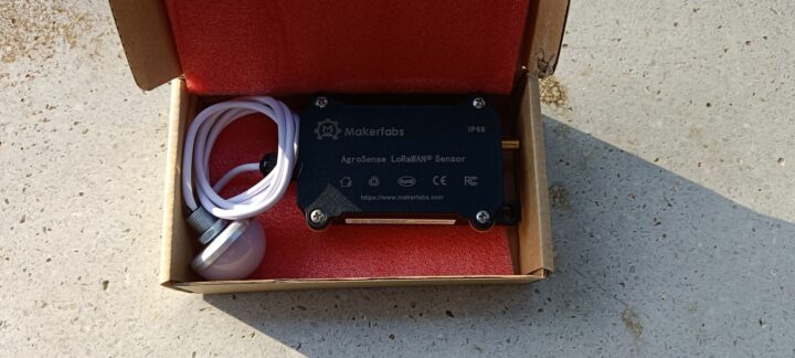
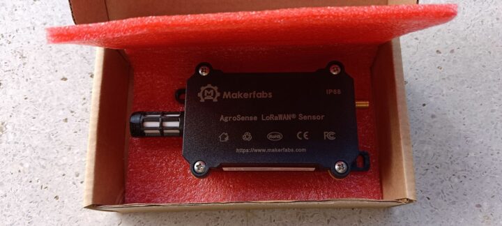
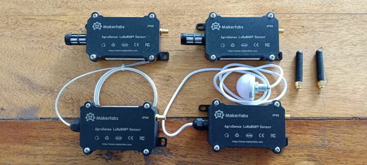
Today, I will be reviewing the AgroSense LoRaWAN sensors from Makerfabs designed for high-precision agriculture. This time, I received four sets of sensors designed for measuring environmental data and a Seeed Studio SenseCAP M2 LoRaWAN gateway. Below is the list of items I received.
- AgroSense LoRaWAN Barometric Pressure Sensor – Measures the barometric pressure in a 300 to 1100 hPa range with ±0.12 hPa accuracy and 0.01 hPa resolution.
- AgroSense LoRaWAN Light Intensity Sensor – Measures the light intensity in a 1 to 65535 lx range with ±1 lx accuracy and ±20% resolution.
- AgroSense LoRaWAN Temperature & Humidity Sensor – Measures temperature and humidity in the atmosphere in the ranges of -40°C to 85°C and 0 to 100 %RH with accuracy of ±0.2°C and ±0.2% RH respectively.
- AgroSense LoRaWAN Industrial Temperature Sensor – Measures temperature in the industrial high-temperature environments in the -60°C to 200°C range with ±0.1°C accuracy and ±0.4% resolution.
- SenseCAP M2 Multi-Platform LoRaWAN Indoor Gateway – A LoRaWAN gateway that supports global LoRaWAN frequency bands from 865 MHz to 923 MHz.
In addition to the above features, the manufacturer also states that the sensors share several common features. For example, they can cover a transmission range of 2 km in urban areas and 5 km in line-of-sight conditions. The sensors are designed for use in harsh environments where the operating temperature can be as low as -40°C or as high as 85°C. They are suitable for outdoor use with an IP68-rated enclosure. Powered by two AAA batteries, they offer a minimum operational lifespan of at least 2 years. Moreover, they come with the DEV EUI, APP EUI, and APP key, making them ready to use and simplifying the installation process.
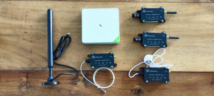
Agrosense LoRAWAN sensors and SenseCap M2 gateway unboxing
Currently, the AgroSense series supports two frequency plans: EU868 and US915, while the gateway supports four: EU868, US915, AS923, and AU915. For this review, Makerfabs send me the US915 version. The manufacturer shipped the samples from China, and they took around one week to arrive at my office in Thailand. The sensors came in a standard brown corrugated box, while the gateway arrived in a larger white corrugated box. All these cardboard boxes were strong and sturdy, as expected.
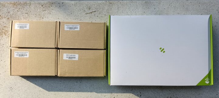
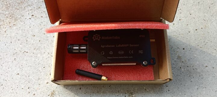
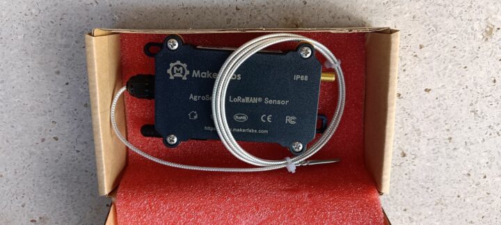
In the case of the AgroSense sensors, each box contained only one AgroSense sensor, except for the AgroSense LoRaWAN Barometric Pressure Sensor and the AgroSense LoRaWAN Temperature & Humidity Sensor, which included an antenna with an SMA connector.
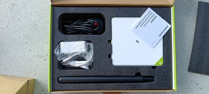
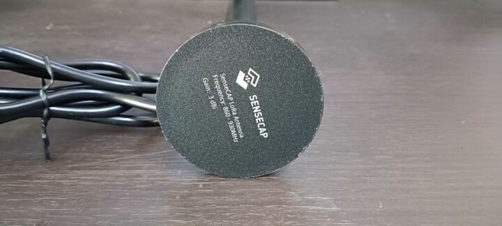
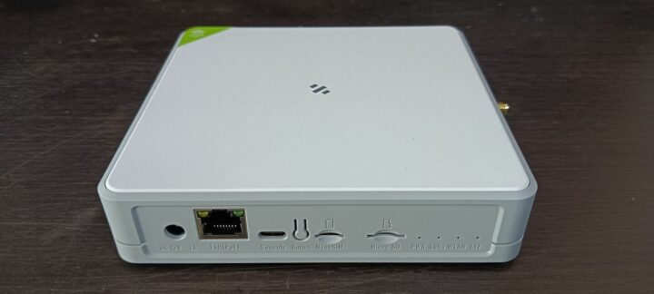
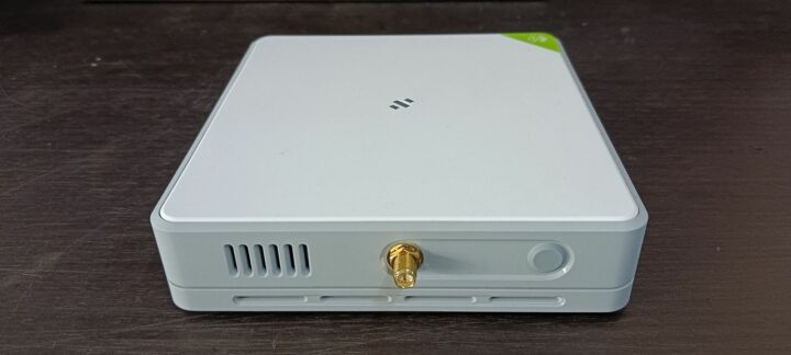
The SenseCAP M2 LoRaWAN indoor gateway was delivered with a 12V DC/2,000mAh adapter and a SenseCAP LoRa Antenna operating at 860 to 930 MHz with 3dBi gain, as shown in the following photos.
Preparing the AgroSense LoRaWAN sensors
I prepared the AgroSense sensors by following the instructions provided on the Makerfabs website. With only two antennas available, I decided to test the AgroSense LoRaWAN Barometric Pressure Sensor and the AgroSense LoRaWAN Temperature & Humidity Sensor. The setup was straightforward. I started by securely attaching the antenna to the enclosure, then opened the top cover to access the module’s components. I inserted two new AAA 1.5V batteries into the battery tray. According to the instructions, pressing the RST button on the mainboard should cause the LED to flash. I confirmed this by pressing the button and observing that the LED flashed, indicating the device was working properly.
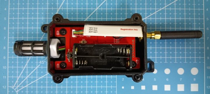
The first time I used the devices, I did not press the button or pay enough attention to the LED, so I was unsure if the devices had successfully started since there is no on/off switch. However, after removing and reinstalling the batteries, I noticed that the LED flashed very briefly once the batteries were fully installed.
Setting Up to SenseCap M2 LoRaWAN gateway
The instructions for setting up the SenseCAP M2 LoRaWAN indoor gateway, available on Makerfabs’s website, state that the overall setup process is easy and can be done using the SenseCAP Mate APP and the SenseCAP Portal. However, some links are broken, and I found detailed instructions suitable for beginners like myself on the SeeedStudio website also pointing to the SenseCAP Portal. Additional documentation is also available as PDF files. I mostly followed the instructions outlined in the Quick Start Guide for SenseCAP Gateway & Sensors PDF file for this review.
My first step was to securely attach the antenna to the gateway, followed by connecting the AC/DC adapter. Upon powering on, the LED on the top cover of the device began flashing slowly in green, indicating that the device was booting. After a moment, the LED turned red, signaling that the Internet connection was not yet established. There are two methods to access the gateway’s configuration page. The first method involves connecting the computer directly to the gateway using an Ethernet cable. The second method is wireless: by pressing the button on the back of the gateway for 5 seconds, you can enable AP mode. The default SSID is named ‘SenseCAP_xxxxxx’, where ‘xxxxxx’ represents the last 6 digits of the MAC address printed on the label at the bottom of the gateway. I tested both methods using a laptop and a smartphone and was able to access the gateway successfully. Once connected, I opened a web browser and logged in to the device using the username and password, which are also printed on the label at the bottom of the device.
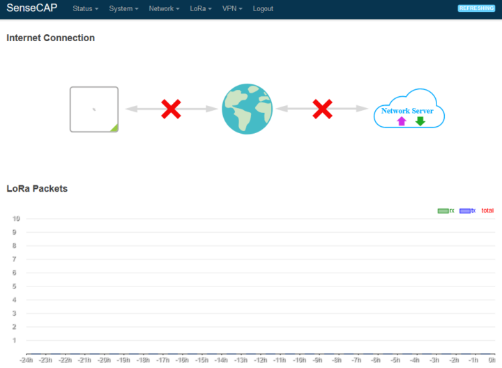
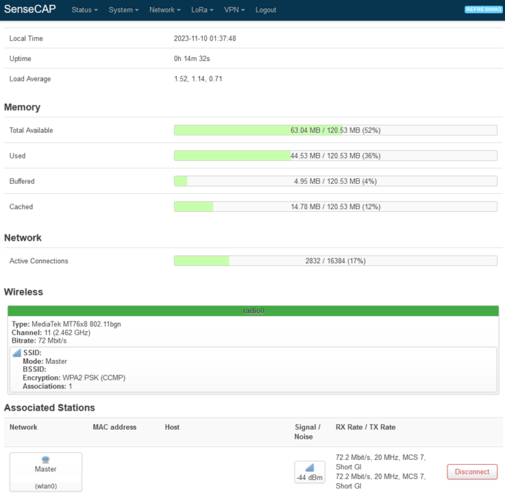
The following figures show screenshots of the main configuration page after my initial login. At this stage, the Internet connection had not yet been configured, and no LoRa packets were being received or transmitted. This page also displays additional information about the hardware, including available memory and network interfaces.
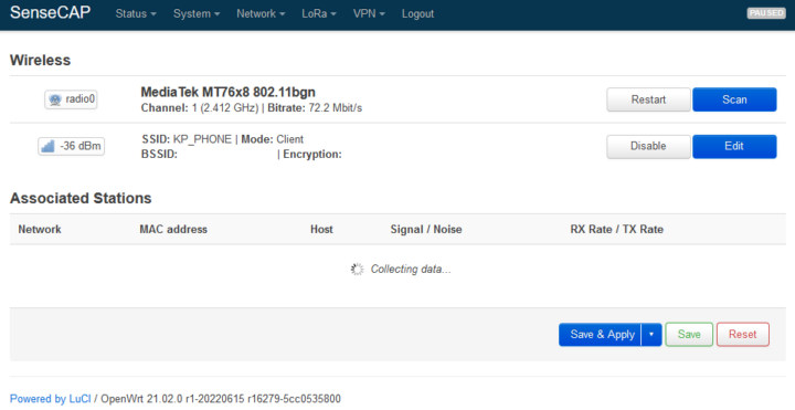
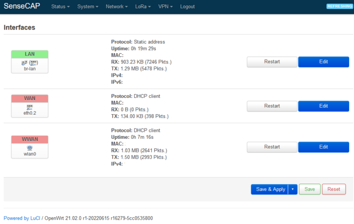
Next, I connected the gateway to the Internet by navigating to the ‘Network’ menu and selecting ‘Wireless’ to scan for available SSIDs. I chose my mobile hotspot SSID from the list, clicked the ‘Join Network’ button, and entered the required information. After submitting the details, I clicked the ‘Save & Apply’ button to apply the configurations. After a short while, the screen refreshed, indicating that the gateway had successfully connected to my hotspot. The LED on top of the gateway turned solid green, showing that the gateway was now online.

Then, I selected the ‘LoRaWAN Network Settings’ menu to configure the target LoRaWAN network. This gateway has four modes: SenseCAP, Packet Forwarder, Basic Station, and Local Network Server. For now, I kept the default setting, which is SenseCAP, as shown in the following figure.

Test connecting with SenseCAP App and SenseCAP Portal
Since the website and instruction manual recommend connecting and configuring the gateway using the SenseCAP Mate App, I downloaded the SenseCAP Mate App on my Android smartphone. My initial attempt to register on the smartphone was successful, but I encountered issues logging in (I did not identify the cause and forgot to capture screenshots). I then tried registering again by using my laptop to directly access the SenseCAP Portal. This registration was successful, and I was able to log in to the SenseCAP Portal website without any problems.
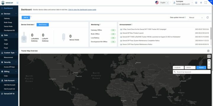
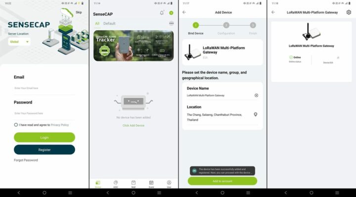
I tried to log in to the portal again using my smartphone, and this time, accessing the SenseCAP Mate App was successful. After that, I used my smartphone to add a new gateway to the system, as shown in the following figures. These processes were completed smoothly.
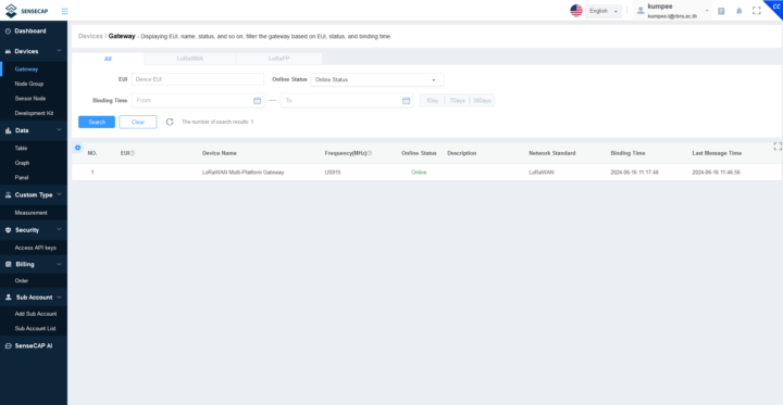
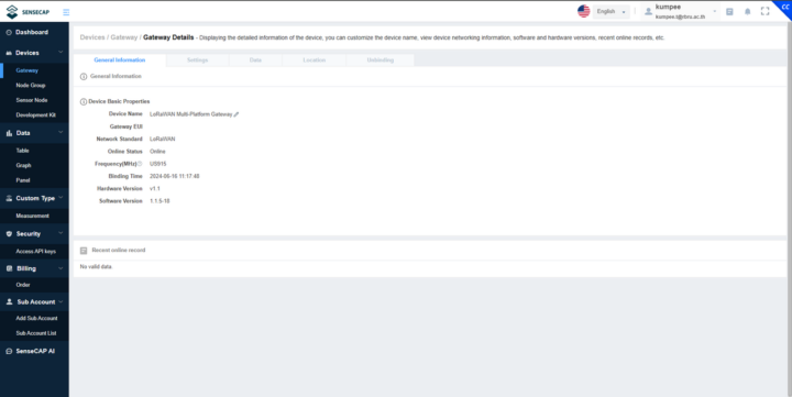
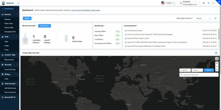
Finally, I navigated to the SenseCAP Portal website to confirm the visibility of the newly added gateway on the web interface. I observed that the gateway was successfully reported online on the SenseCAP Portal, as shown in the following screenshots.
Connecting the gateway to The Things Network
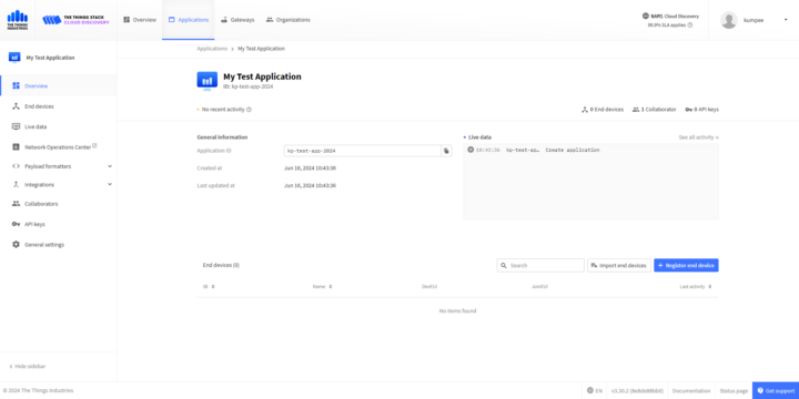
To test the gateway and the sensors with The Things Network, I proceeded to create a new Application within The Things Network platform. For this review, I named the Application ‘My Test Application’ and assigned it the application ID ‘kp-test-app-2024.’ Upon entering the required details, I successfully created the new Application, as shown in the following figure.
Next, I returned to the gateway to adjust the ‘LoRaWAN Network Settings’. To configure the gateway for integration with The Things Network, I changed the ‘Mode’ setting to ‘Packet Forwarder’ and entered the Application ID and other parameters obtained from The Things Network. The result of applying these settings is shown in the following figure.

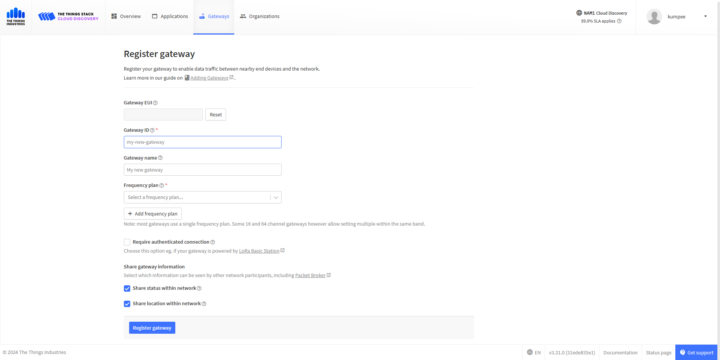
The next step involved registering the gateway with The Things Network. I filled in several parameters, including the Gateway EUI and the gateway’s name. I selected the Frequency plan option ‘United States 902-928 MHz, FSB 2 (used by TTN)’ and then pressed the ‘Register gateway’ button to complete the registration process.
The next step is to add the sensors to the platform. Instructions for adding the AgroSense LoRaWAN sensors to The Things Network are available on the Makerfabs website. Generally, all of the sensors use the same settings for the ‘Frequency plan’, ‘LoRaWAN version’, and ‘Regional Parameters version’, as detailed below.
- Frequency plan: United States 902-928 MHz, FSB 2 (used by TTN)
- LoRaWAN version: LoRaWAN Specification 1.0.2
- Regional Parameters version: RP001 Regional Parameters 1.0.2
The data required for filling in the ‘Provisioning Information’ section for each sensor is printed on a sticker on the sensor enclosure. The mapping between AgroSense LoRaWAN fields and The Things Network fields is as follows:
- APP EUI <–> JoinEUI
- DEV EUI <–> DevEUI
- APP KEY <–> AppKey
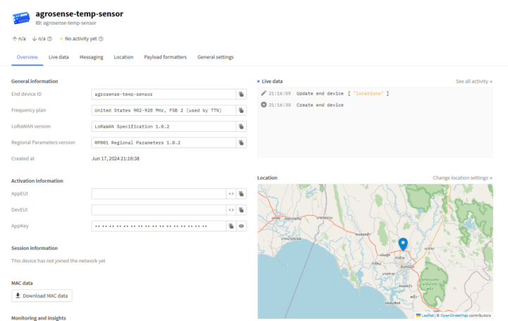
The following figure shows an overview of the sensor in The Things Network. Since the sensor lacks a GNSS receiver, I manually set the mapping coordinates to a location near my office.
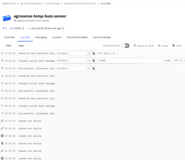
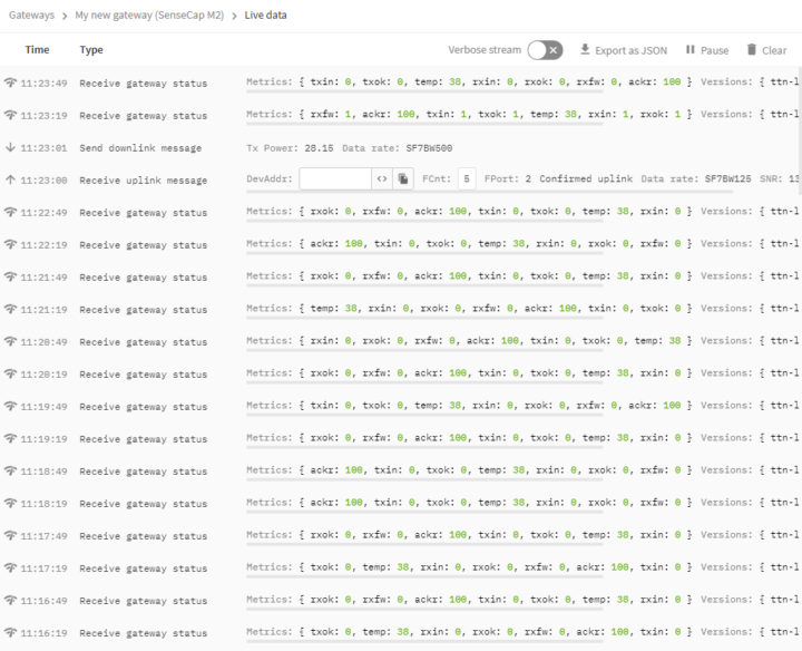
After waiting patiently for a brief moment, I observed that the live data frame was successfully updated with the latest sensor data, confirming that the communication between the sensor, the gateway, and The Things Network was operating smoothly as shown in the following figure.
Test requesting data from The Things Network
I was new to The Things Network and, for this review, I wanted to store the sensor data temporarily for later use in other applications. After a brief search on the Internet, I found that I needed an API key and had to enable the Storage Integration option. Therefore, I opened the ‘Applications’ menu, followed by ‘API keys’, and then clicked ‘+ Add API key’. After filling in the required fields, I obtained the API key.
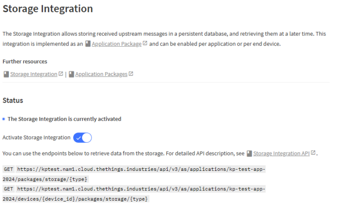
To enable the Storage Integration, I had to select ‘Applications’, followed by ‘Integrations’, and then ‘Storage Integration’. After activating the Storage Integration option, the system displayed the endpoints for pulling data via the Storage Integration API, as shown in the following figure. In my case, the current version of the API was v3. More information about the API can be found on the Storage Integration API web pages. I found that the AgroSense LoRaWAN sensors update their measurements every hour. So, I let the end devices and the gateway send data to The Things Network for 8-10 hours before testing data requests with the Storage Integration API.
In this review, I used Python 3.8 to perform the request, using the Requests, JSON, and base64 packages. I also had to add the API key to the Bearer Authorization section and included some additional parameters in the HTTP request header. The data returned by The Things Network was in JSON format. However, there was a minor issue: each measurement data section was separated by a space instead of using a comma. After resolving this issue, I was able to extract the measurement data successfully.
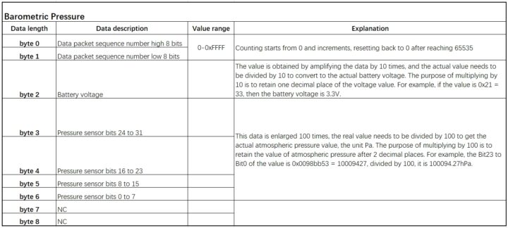
The data is embedded in the ‘frm_payload’ section and is a base64 encoded string. The result of decoding this will be a byte array, which may differ for each sensor. Information about how to interpret these byte arrays can be found in the Makerfabs instruction manual we already used when assembling the sensors. The data structure for the AgroSense LoRaWAN Barometric Pressure Sensor is outlined in the table below. To extract the battery voltage, divide the 2nd byte by 10. The air pressure value is derived from bytes 3 to 6, which are combined to form a 24-bit integer. This integer is then divided by 100 to obtain the air pressure in hPa.
For the AgroSense LoRaWAN Temperature & Humidity Sensor, the humidity value is located in bytes 3 and 4, while the temperature value is found in the subsequent 2 bytes. To obtain the output values, use a similar approach as described previously, but divide by 10 instead of 100.

The figure below visualizes the data from the AgroSense LoRaWAN Barometric Pressure Sensor and the AgroSense LoRaWAN Temperature & Humidity Sensor during the testing period.

Here is a simple Python code snippet I used to request data from The Things Network through the Storage Integration API.
|
1 2 3 4 5 6 7 8 9 10 11 12 13 14 15 16 17 18 19 20 21 22 23 24 25 26 27 28 29 30 31 32 33 34 35 36 37 38 39 40 41 42 43 44 45 46 47 48 49 50 51 52 53 54 55 56 57 58 59 60 61 62 63 64 65 66 67 68 69 70 71 72 73 74 75 76 77 78 79 80 81 82 83 84 85 86 87 88 89 90 91 92 93 94 95 96 97 98 99 100 101 |
import requests import json import base64 def decode_ttn_payload(x): y = base64.b64decode(x) return y def extract_temp_hum_value(b): seq = int.from_bytes(b[0:2], byteorder='big', signed=False) bat = int.from_bytes(b[2:3], byteorder='big', signed=False)/10.0 rh = int.from_bytes(b[3:5], byteorder='big', signed=False)/10.0 tem = int.from_bytes(b[5:7], byteorder='big', signed=False)/10.0 return seq, bat, rh, tem def extract_baro_pres_value(b): seq = int.from_bytes(b[0:2], byteorder='big', signed=False) bat = int.from_bytes(b[2:3], byteorder='big', signed=False)/10.0 atm = int.from_bytes(b[3:7], byteorder='big', signed=False)/100.0 return seq, bat, atm def main(): n_data_limit = 800 target_date = "2024-06-17" start_time = "{:}T00:00:00Z".format(target_date) end_time = "{:}T23:59:59Z".format(target_date) params = { "start": start_time, "end": end_time, } params = {} app_id = "123456" api_key = "ABCDEF" #target_device_id = "agrosense-baro-pres-sensor" target_device_id = "agrosense-temp-hum-sensor" url = "https://kptest.nam1.cloud.thethings.industries/api/v3/as/applications/{:}/devices/{:}/packages/storage/uplink_message?limit={:}&order=received_at".format( app_id, target_device_id, n_data_limit) headers = {"Authorization": "Bearer {:}".format(api_key),} response = requests.get(url, headers=headers, params=params) if response.status_code == 200: try: data_str = response.text data_array = data_str.split("\n") n_data = len(data_array) f_out = open("output_{:}.txt".format(target_device_id), "w") for i in range(0, n_data, 1): if(len(data_array[i]) < 10): continue data_json = json.loads(data_array[i]) result = data_json["result"] end_device_ids = result["end_device_ids"] device_id = end_device_ids["device_id"] received_at = result["received_at"] uplink_message = result["uplink_message"] frm_payload = uplink_message["frm_payload"] decoded_payload = decode_ttn_payload(frm_payload) received_datetime = received_at.split("T") if(device_id == "agrosense-baro-pres-sensor"): seq = extract_baro_pres_value(decoded_payload) ... elif(device_id == "agrosense-temp-hum-sensor"): seq = extract_temp_hum_value(decoded_payload) f_out.write("{:},{:},{:},{:},{:},{:},{:},{:}\n".format( received_datetime[0], received_datetime[1][0:10], device_id, frm_payload, seq[0], seq[1], seq[2], seq[3],)) print("{:} | {:} | {:<28s} | {:} | {:}".format( received_datetime[0], received_datetime[1], device_id, frm_payload, seq)) ... f_out.close() except Exception as error: print("cannot convert to json") print(error) else: ... if __name__ == "__main__": main() |
A closer look at the sensors
The sensors I received for this review are housed in a robust plastic enclosure. A 2mm-thick silicone rubber seal is positioned between the top and bottom parts of the enclosure. The top section features screen-printed information including the manufacturer, product name, and additional values and symbols. On one side of the enclosure, a sticker displays the EUIs and Keys, while another sticker on the opposite side provides extra product details. The top cover is secured with four screws, which were not too tightly fastened and were easily removed. When opened, the silicone rubber remains attached to the top cover, and all internal components are housed in the bottom part.
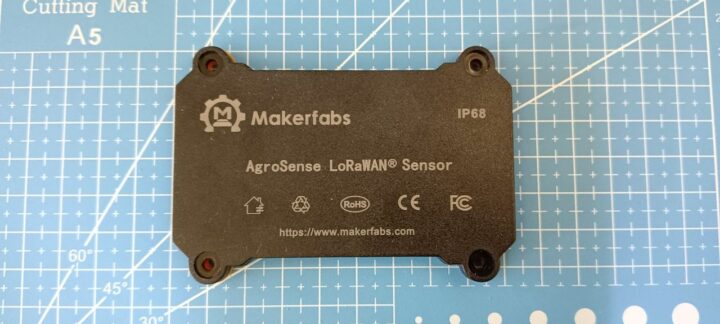
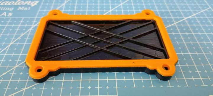
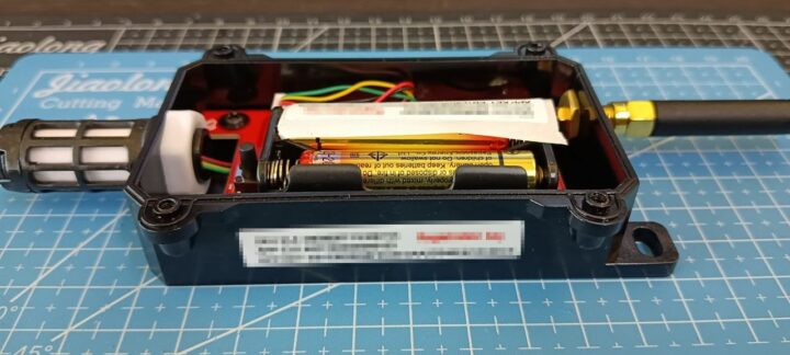
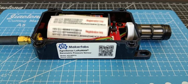
The main PCB features a red solder mask and white silkscreen. On the top of the PCB, there is a battery holder designed to take two 1.5V AAA batteries. Additionally, the board includes one LED and two push switches labeled RST and USER. There are also two connectors for attaching sensors, labeled J1 and J3. The enclosure is equipped with a cable gland to protect the internal electronics from moisture and water. An IPEX connector on the PCB connects to an external SMA connector for antenna attachment.
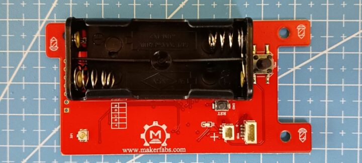
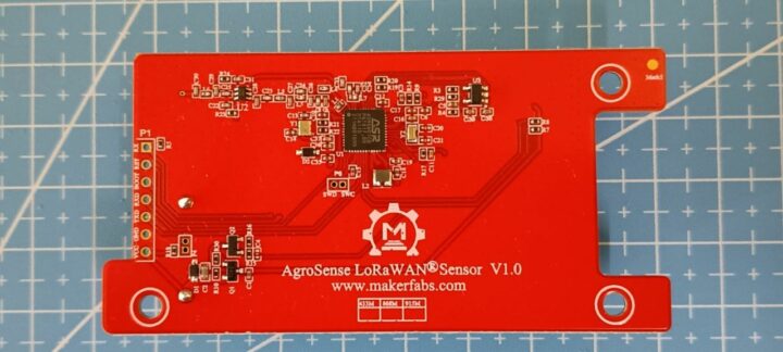
To inspect the other side of the PCB, I removed the three screws, the sensor, and the antenna. On the bottom side of the PCB, I discovered that the largest chip is the ASR6601CB, which is a general LPWAN wireless communication SoC with an integrated RF transceiver. Additionally, there is a 7-pin connector labeled P1, with pins marked as VCC, GND, TXD, RXD, BOOT, RST, and RX. However, I was unable to find any information on how to use these pins.
Test communication range
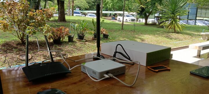
I conducted this testing at my office, placing the gateway in the multi-purpose yard in front of the Faculty of Computer Science and Information Technology, Rambhai Barni Rajabhat University. I pressed the USER switch on the sensor to observe the RSSI and SNR values reported on The Things Network. In the first attempt, with the gateway and sensor approximately 1 meter apart, the RSSI and SNR values were around -23 dB and 13.5, respectively. I then moved the sensor to five different locations, as illustrated in the following figure.
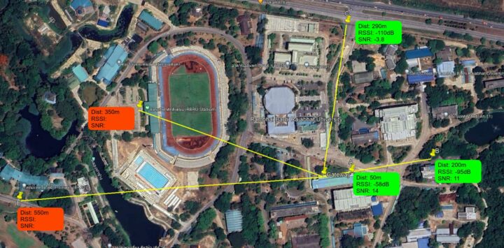
As a result, I successfully received the signal from the sensor at locations A and B without any issues. The farthest distance from the gateway during this test was at location C, approximately 290 meters away. At locations D and E, however, the gateway was unable to receive any data from the sensor, as the Live data frame on The Things Network did not update at these locations. This test was conducted using the provided antennas and the gateway’s default settings, without any optimization. Additionally, it was raining during the test. While it was very cloudy at locations A and B, there was heavy rain by the time I reached locations D and E. Therefore, I decided to end the test. [Update: However since I tested the devices in an area where buildings or other obstacles may affect the signal strength, and Makerfabs confirmed a communication range of at least 2 km in line-of-sight conditions, I will try to retest the devices again after the rainy season.]
AgroSense sensors’ power consumption
In this review, I used Panasonic ALKALINE AAA LR03 1.5V batteries, produced in February 2024, which I purchased from a convenience store. I activated the AgroSense LoRaWAN Temperature & Humidity Sensor on June 18, 2024, at 8:45 AM. At that time, The Things Network reported a voltage of 3.1V, while a manual measurement with a multimeter showed 3.25V. The sensor operated continuously until July 5, 2024, at 8:26 PM, approximately 17 days. During this period, The Things Network reported a voltage of 2.3V, and a manual measurement indicated 2.44V. The following figure illustrates the voltage drop over the 17 days of testing for the AgroSense LoRaWAN Temperature & Humidity Sensor. In contrast, the AgroSense LoRaWAN Barometric Pressure Sensor, which was tested simultaneously, showed almost identical battery levels on the first and last days, with voltages of 3.0V (3.22V when manually measured with a multimeter). However, I was unable to confirm the battery life over an extended period due to time constraints, so I could not verify if the batteries would last up to one year as stated by the manufacturer.

[Update: Makerfabs explained that in the case of the AgroSense LoRaWAN Temperature & Humidity Sensor, the connection between the AgroSense sensor and the gateway failed for some reason. As a result, the sensor tried to connect to the gateway every 5 minutes for an hour, which consumed much more power than in normal usage conditions. Makerfabs also stated that in their testing over 3 months, there was a very low power drop with two AAA batteries. Therefore, theoretically, the sensor should last for more than a year.]
Conclusions
In conclusion, the AgroSense LoRaWAN sensors and SenseCAP M2 gateway are easy to use and perform as expected. As mentioned earlier, this was my first experience with LoRaWAN devices, and I was initially concerned about unfamiliar technical terms and the complexity of the setup process. Fortunately, it took me less than an hour to understand the workflow and complete the setup without any major issues.
One behavior of the gateway that I need to mention is that, even though I changed the mode of the ‘LoRaWAN Network Settings’ to ‘Packet Forwarder’ to send data to The Things Network, I found that the device continues to send its status (along with some unknown parameters) to the SenseCAP Portal approximately every 5 minutes.
I also received an email from the manufacturer stating that, with the current firmware (as of July 2024), the data reported by the AgroSense sensors reflects measurements from 60 minutes earlier than the actual data transmission time. For example, data transmitted at 11 AM is measured at 10 AM. The manufacturer informed me that they are working on this issue to improve the devices’ suitability for real-time applications.
I would like to thank Makerfabs for providing these LoRaWAN devices for this review. You can purchase AgroSense LoRaWAN sensors from Makerfabs’ website. The Barometric Pressure Sensor, Light Intensity Sensor, Temperature & Humidity Sensor, and Industrial Temperature Sensor are all priced at $24.90 each. The SenseCAP M2 gateway is available for $99.00 and can be purchased from both Makerfabs and Seeed Studio websites.

My main research areas are digital image/audio processing, digital photogrammetry, AI, IoT, and UAV. I am open to other subjects as well.
Support CNX Software! Donate via cryptocurrencies, become a Patron on Patreon, or purchase goods on Amazon or Aliexpress


