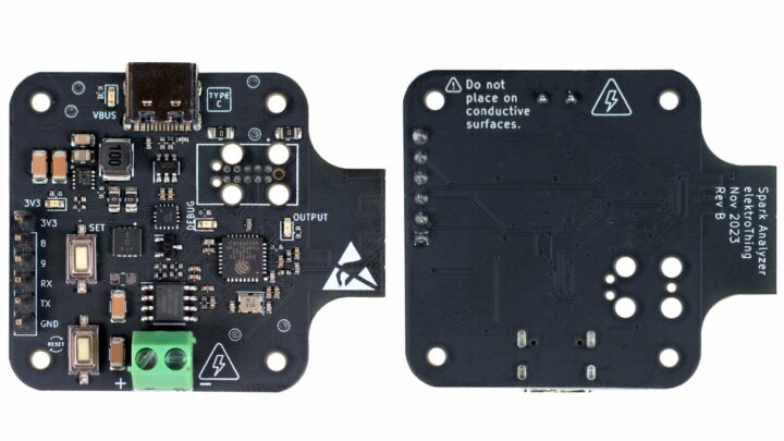
Spark Analyzer is an ESP32-C3-powered device built to streamline the process of developing and debugging USB-C Power Delivery (UCPD) solutions. The board’s design is simple, compact, and includes helpful power delivery and analysis functionality, at an affordable price.
Spark Analyzer runs on an ESP32-C3FH4 microcontroller, a low-power SoC with a single-core RISC-V CPU with onboard 2.4 GHz Wi-Fi and Bluetooth 5 (Low Energy) connectivity. The wireless chip lets users control the Spark Analyzer and monitor its operation remotely. It also supports integration with other smart devices via Matter.
The device allows you to adjust voltage output from 5V to 20V, depending on your project requirements. Power is sent to a connected device via the two-pin screw terminal block on the device, and a Cross Chip sensor measures the electrical current sent through the device using Hall effect. It includes a software safety feature that turns off the output field-effect transistor (FET) when the current is too high. The current draw can be monitored in real time via a mobile app.
Spark Analyzer specifications:
- Microcontroller – ESP32-C3FH4 RISC-V MCU with 4 MB flash memory
- Wireless – Wi-Fi 802.11b/g/n, Bluetooth 5 (LE) on ESP32-C3
- USB – USB Type-C port for programming and power delivery
- Misc – 3x LED indicators (power on, output enable, programmable LED/debug), 2x buttons (reset, programmable button/debug)
- Power Supply via USB-C port
- Negotiable Power Delivery: 5 VDC, 9 VDC, 12 VDC, 15 VDC, 20 VDC; max 5 A (100 W at 20 VDC)
- ON Semiconductor FUSB302MPX: Programmable USB Type-C control and USB PD communication
- Electrostatic Discharge Protection: On D+/D-/CC1/CC2 pins
- Texas Instruments TPS62175DQCT: 3.3 VDC 0.5 A max output DC-DC Step-Down Converter
- Power Output: 3.5 mm, 2-position terminal block
- I/O
- GPIO – 4x GPIOs (I2C, UART, SPI compatible)
- Power Pins – 5 VDC and GND
- Programming – Built-in USB JTAG programmer (ESP32-C3) via USB-C port, compatible with Arduino.
- Output
- Current Output: CC6904SO-10A (Hall Effect Current Sensor)
- Output Enable: DMP3017SFG-7 MOSFET
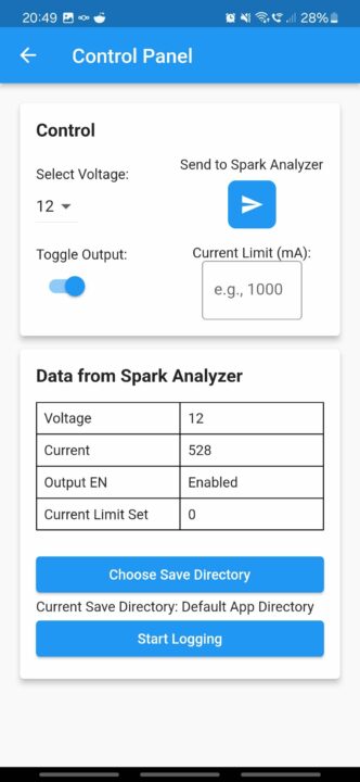
The Spark Analyzer Mobile App is available for download on Android, while iOS support is available via the RemoteXY app. The app displays data from the Spark Analyzer and allows you to control the device in real time. You can save the current draw as a .csv file and set the current limit using your phone.
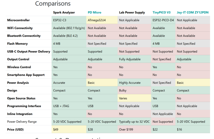
The project is open-source and the GitHub repository contains detailed project documentation: code, hardware schematics, 3D enclosure files, and usage instructions. The Spark Analyzer compares favorably with alternatives on the market, with wireless connectivity being its most remarkable feature.
The Spark Analyzer is currently live on Crowd Supply with a $1500 funding goal. It is priced at $49, with free shipping within the United States and a $12 shipping fee to the rest of the world. Orders are expected to ship by August 4, 2024.

Tomisin is a writer specializing in hardware product reviews, comparisons, and explainers. He is very passionate about small form factor and single-board computers.
Support CNX Software! Donate via cryptocurrencies, become a Patron on Patreon, or purchase goods on Amazon or Aliexpress


