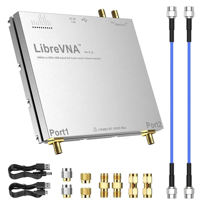
Jan Käberich’s LibreVNA is an open-source hardware USB vector network analyzer (VNA) based on a Spartan-6 FPGA, an STM32 microcontroller, and RF circuitry with MAX2871 and Si5351C chips. The open-source VNA supports two channels and works in the 100kHz to 6GHz frequency range.
Vector network analyzers are expensive pieces of electronic test equipment used to measure the magnitude and phase of high-frequency electrical networks costing several thousand dollars. They are commonly used in radio frequency (RF) and microwave engineering applications. Last year, we wrote that Pico Technology released PicoVNA 5 software for Linux, Raspberry Pi, and macOS instead of only providing a Windows program for their commercial PicoVNA devices. I thought it was already a good development even if it was closed-sourced, but LibreVNA goes all the way with an open-source hardware design with hardware design files, the FPGA code, STM32 firmware, and PC software (GUI) all open-source.
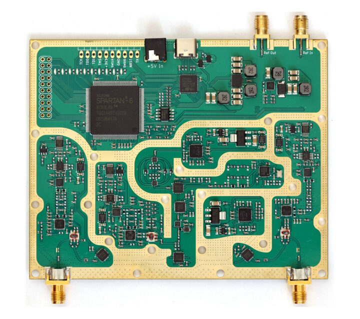 LivreVNA hardware specifications:
- FPGA – Spartan6 FPGA handles communication with the RF blocks and samples the ADCs.
- MCU – STM32G431 microcontroller handles the setup of the sweep in the FPGA, extracts and preprocesses the measurements, and passes them on through USB.
- Storage – Flash for the FPGA bitstream. The microcontroller can also access the flash, so no FPGA-related hardware tools (such as JTAG programmers) are needed and everything can be updated via USB
- Clock sources
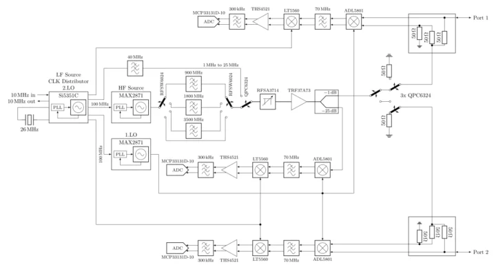
- A Skyworks Si5351C clock generator provides all the required clocks and serves as the stimulus source for frequencies below 25MHz. Its reference clock is either a 26MHz crystal or an external 10MHz signal.
- Analog Device MAX2871 is the stimulus source for frequencies above 25MHz, its output signal is slightly filtered to reduce the number of harmonics and can be adjusted between approximately -42 and -10dbm with a digital attenuator (RFSA3714).
- After the TR37A73 amplifier, the signal is split
- The weaker part of it is fed into the reference receiver.
- The stronger part of the signal can be routed to either port, each having 2x RF switches used in series to achieve higher isolation between the ports.
- Both ports have completely separated receive paths to measure two parameters at once (S11 and S21 or S22 and S12).
- Each receiver consists of two down-convert mixers. The 1.IF sits at 60MHz, the 2.IF 250kHz.
- ADCs are sampling the final IF with 16-bit @ 800kHz.
- Power Supply – 5V via USB-C port or external 5V DC
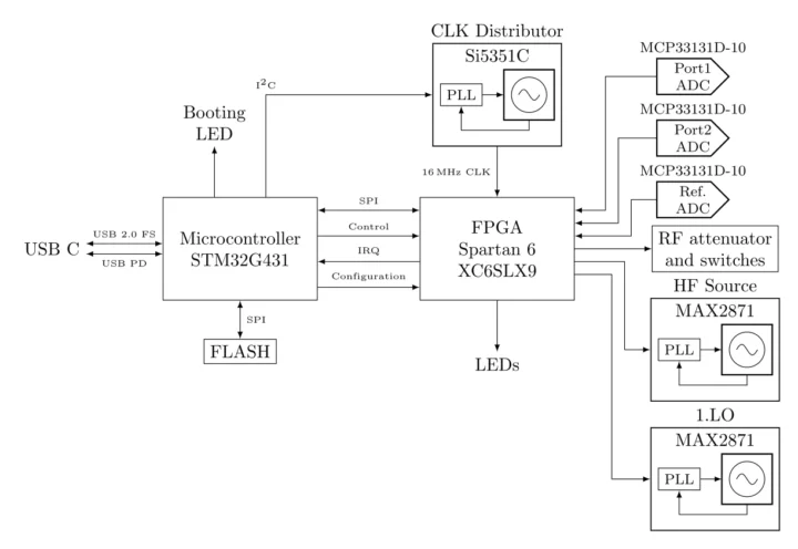
Jan explains the LibreVNA PCB is just an RF frontend with some processing power used to capture the data and send it to the host over USB. Actual data processing is done in the LibreVNA-GUI PC application with pre-built binaries available for Windows, Ubuntu, macOS, and even the Raspberry Pi 5. That means you can try it out without the PCB simply importing example measurements.
I tried that on a Ubuntu 22.04 laptop, and after installing some extra dependencies, the program could start.
|
1 2 3 |
sudo apt install libqt6widgets6 libqt6svg6 libqt6network6 qt6-wayland unzip LibreVNA-GUI-Ubuntu-v1.5.0.zip ./LibreVNA |
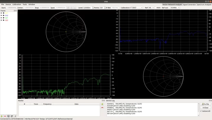
I could also import measurement examples (Documentation/Measurements folder) in LibreVNA-GUI, but somehow the data would not show… Here’s one of the sample measurement from a screenshot provided by the developer.
It can also serve as a signal generator or spectrum analyzer. RF engineers may find the solution interesting and can access all resources to get started or build their own on GitHub. The project is not entirely new, so the hardware can be purchased on Amazon or Aliexpress for around $500 and up with an enclosure and accessories.
Via Hacker News

Jean-Luc started CNX Software in 2010 as a part-time endeavor, before quitting his job as a software engineering manager, and starting to write daily news, and reviews full time later in 2011.
Support CNX Software! Donate via cryptocurrencies, become a Patron on Patreon, or purchase goods on Amazon or Aliexpress


