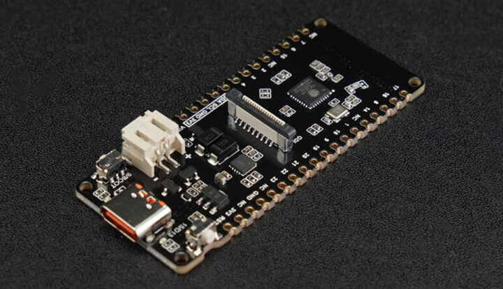
DFRobot’s FireBeetle 2 ESP32-C6 is an IoT Development Board with 802.11ax (now called Wi-Fi 6), Bluetooth 5, Zigbee 3.0, Thread 1.3, and flexible power options including USB Type-C, 5V DC, and a CN3165 Lithium Ion battery charger for solar-powered systems.
This isn’t the first solar-based board we’ve covered. We’ve also explored boards like Conexio Stratus, Wisblock Kit 2, and RAK8211-NB iTracker along with other solar-powered devices such as solar-powered laptops, solar-powered headphones, and even a solar-based power supply.
FireBeetle 2 ESP32-C6 IoT Development Board Specifications:
- Processor – ESP32-C6 RISC-V single-core, 160 MHz
- Memory
- SRAM – 512KB
- ROM – 320KB
- Flash – 4MB
- RTC SRAM – 16KB
- USB – USB 2.0 CDC
- Wi-Fi
- Protocols – IEEE 802.11b/g/n, IEEE 802.11ax (20 MHz-only non-AP mode)
- Bandwidth – Supports 20 MHz and 40 MHz at 2.4 GHz
- Modes – Station, SoftAP, SoftAP+Station
- Frequency – 2.4GHz
- Frame Aggregation – TX/RX A-MPDU, TX/RX A-MSDU
- Bluetooth
- Protocol – Bluetooth 5, Bluetooth mesh
- Frequency – 125 Kbps, 500 Kbps, 1 Mbps, 2 Mbps
- IEEE 802.15.4
- Compatibility – IEEE 802.15.4-2015 protocol
- Frequency Band – 2.4GHz
- Data Rate – 250Kbps
- Supports – Thread 1.3 and Zigbee 3.0
- Ports and Interfaces:
- Digital I/O – 19x
- LED PWM – 6 Channel
- SPI – 1x
- UART – 3x (LP UART x1)
- I2C – 2x (LP I2C x1)
- I2S – 1x
- IR Transceiver – 5x transmit channel, 5x receive channel
- ADC – 1x 12-bit SAR, 7 Channel
- DMA Controller – 3x transmit channel, 3x receive channel
- Other Parameters:
- Operating Voltage – 3.3V
- Type-C Input Voltage – 5V DC
- Solar Input Voltage – 4.5 – 6V Solar Panel
- Max Charging Current – 0.5A
- Sleep Current – 16uA (in deep sleep mode, powered by battery)
- Operating Temperature – -10~60
- Dimensions – 25.4x60mm / 1×2.36”
The board has been designed to support power from three different sources. Firstly, it can be powered or programmed via a USB-C connection. Secondly, it accepts external power up to 5V through the VCC pin. Lastly, it can be powered from an external battery using the provided JST connector.

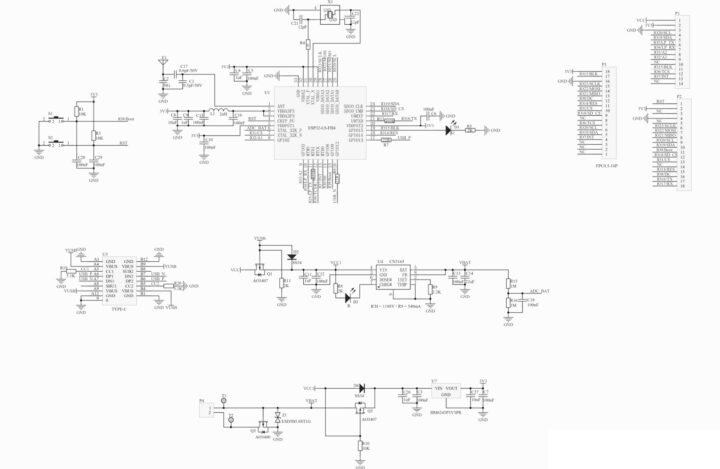
From the schematic, it’s clear that the board uses a CN3165 constant-current /constant-voltage linear charger IC to convert the solar power and charge the battery. According to the datasheet, this IC can charge the battery with a maximum constant current of 1A, and it also allows setting the current with a resistor. Additionally, the schematic shows the use of an HM6245P3V3PR High input voltage, 85 mA LDO linear regulator, to convert external power to 3.3V, which then powers the ESP32-C6 module.

Another interesting feature of this board is that it supports Wi-Fi 6’s Target Wake Time (TWT) technology that lowers power consumption, and enhances battery life and device performance.
The device also supports Thread 1.3. it is a wireless mesh networking protocol designed for Internet of Things (IoT) applications. It enables seamless integration into IoT networks with various communication protocols, making it an ideal solution for smart home and commercial building environments.
In the box, you will fid one FireBeetle 2 Board ESP32 C6 Microcontroller and two sets of 20-pin 2.54mm pin headers. The product page also includes additional documentation including a product wiki, the ESP32-C6 chip datasheet, schematics, and dimension details. They also provide project examples using the Arduino IDE and how-to guides on the product page.
The FireBeetle 2 ESP32 C6 IoT development board can be purchased directly from DFRobot or you can buy it from Aliexpress. In both outlets, it is priced at $5.90.
Debashis Das is a technical content writer and embedded engineer with over five years of experience in the industry. With expertise in Embedded C, PCB Design, and SEO optimization, he effectively blends difficult technical topics with clear communication
Support CNX Software! Donate via cryptocurrencies, become a Patron on Patreon, or purchase goods on Amazon or Aliexpress


