Hello, I’m excited to review the ESP32 display modules and HMI touchscreens from Elecrow with sizes ranging from 2.4 to 7.0 inches. For this review, Elecrow kindly provided me with both 3.5-inch and 7.0-inch models. While their screens differ in size, both modules share several components, such as the ESP32 microcontroller, making them adaptable options for a variety of projects.
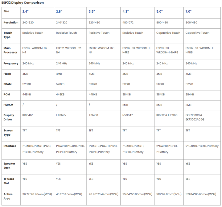
The Elecrow 7.0-inch display module is powered by the ESP32-S3-WROOM-1-N4R8 module equipped with an ESP32-S3 dual-core LX6 32-bit microprocessor, 4 MB of flash, 384 kB of ROM, and 512 kB of SRAM. This microcontroller supports both WiFi and Bluetooth for wireless communication. The 7.0-inch display itself is a capacitive touch screen with a resolution of 800×480 pixels. The display is controlled by the EK9716BD3/EK73002ACGB driver and is compatible with LVGL for additional functionality.
In the case of the 3.5-inch display module, the main difference is the use of the ESP32-WROOM-32-N4 module based on the ESP32 dual-core LX6 processor with 520 kB of SRAM (slightly more than the 7.0-inch version). The display is an LCD resistive touch screen with a resolution of 320×480 pixels, and it is controlled by the ILI9488 driver.
The device supports programming through various IDEs, frameworks, and languages including the Arduino IDE, the Espressif IDF, PlatformIO, and MicroPython. Additionally, both modules are equipped with I2C connectors and GPIO pins for expansion. The devices also support UART connections, and further details and specifications can be found in the manufacturer’s summary table below.
Unboxing Elecrow ESP32 display modules
The two sample displays were securely packaged in a cardboard box and shipped from China. Upon opening the box, I found the bubble wrap wrapped around the two screens, where each screen was packed separately in its own cardboard box. The size of the cardboard boxes and the bubble wrap were just right. When handled, the package felt sturdy and secure. The assembly of the components on the PCBs was done neatly. The PCBs used red solder masks and white silkscreen.
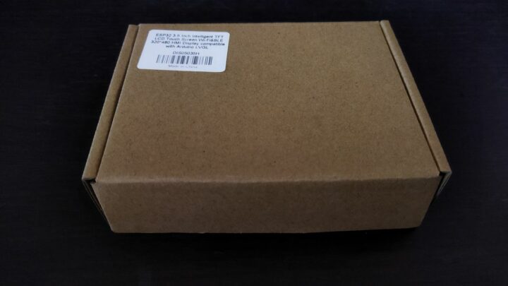
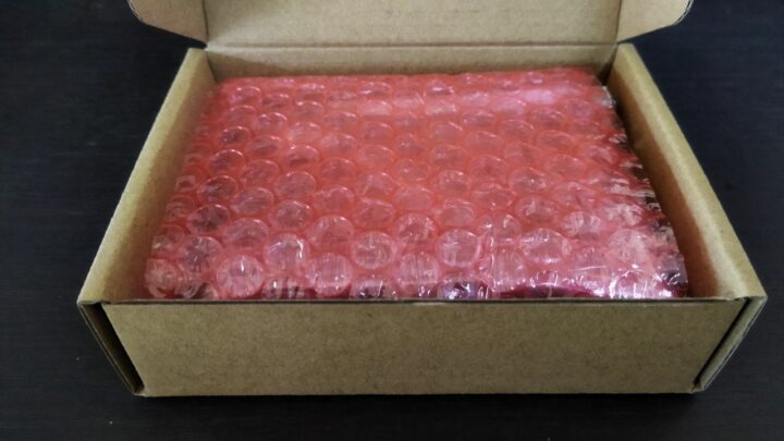
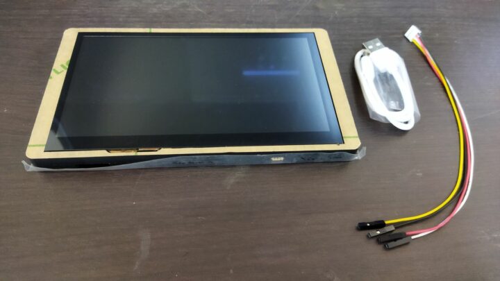
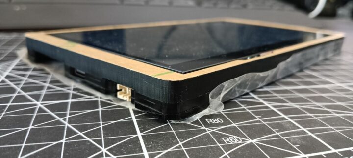
Inside the box of the 7-inch screen, there was one screen set, one Crowtail/Grove to 4-pin DuPont cable, and one USB Type-C cable. In addition, the manufacturer also provided a case for the screen made of 6-mm thick acrylic sheets. In my case, the manufacturer already assembled the screen module into the acrylic case and securely fastened it with screws.
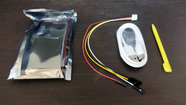
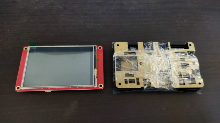
The packaging of the 3.5-inch screen module was also well-designed and provided adequate protection for the product. Inside the box, I found one screen set, a stylus for interacting with the screen, one Crowtail/Grove to 4-pin DuPont cable, and one USB Type-C cable. The manufacturer also provided an acrylic case, but it is not yet assembled. Assembling the display module into the acrylic case results in a similar experience, providing a sturdy and well-built feel with good thickness.
Testing with factory firmware
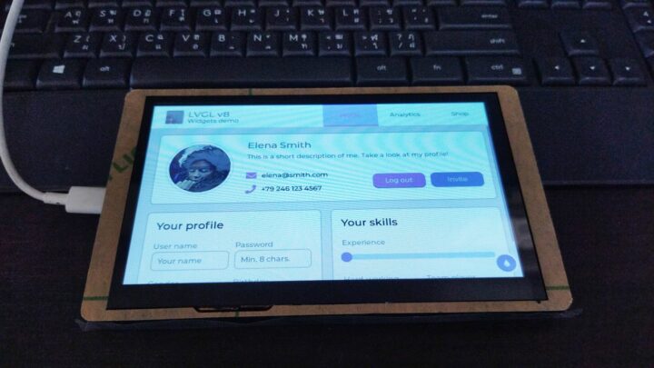
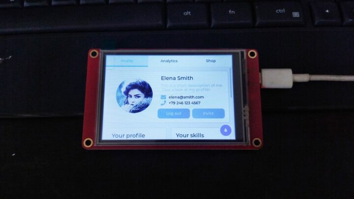
During my initial test, I connected the display to my laptop using the provided USB Type-C cable and plugged it into the USB port on the boards. When the devices started up, they displayed the same factory demo code, as seen on the manufacturer’s website and YouTube. I proceeded to interact by touching various UI elements on the screens with my fingers and the pen provided. Overall, I found that it worked normally, but it might not be as smooth or responsive as in the promotional videos. The sharpness and brightness of the colors were also at a normal level for this type of screen. The viewing angles are somewhat limited by the characteristics of TN display panels. It may not match the performance of IPS displays, but the display is still suitable for various applications.
Flashing the Factory Demo Program using the Arduino IDE
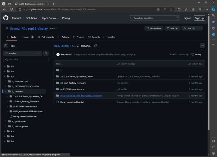
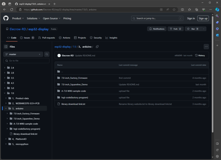
The devices support development through various IDEs as mentioned above, but in this review, I decided to test them with the Arduino IDE. The manufacturer provided guides explaining the necessary steps to install the required library, available on their website, along with video demonstrations on YouTube. However, in the beginning, I was a bit confused about where to find the sample codes or details of the necessary libraries. This is because the information on the website and the sample videos on YouTube differ in many places. However, after spending a while, I found that the information needed for flashing the program is easier to follow if you look at the Wiki for the 7-inch screen and the 3.5-inch screen. You can also find the sample code from the manufacturer’s GitHub repository.
Preparing the Arduino IDE
The installation guide does not specify the version of Arduino IDE. The website and the YouTube video examples use Arduino IDE version 1.8.19. However, for this review, I wanted to test whether using a newer version of Arduino IDE would cause any problems. Therefore, I chose to install the latest version of Arduino IDE, which at the time of writing this review is version 2.2.1.
After preparing the IDE, I downloaded the necessary file as instructed on the manufacturer’s website. In summary, we can use the Arduino_35.zip for the 3.5-inch screen and the Arduino_7inch.zip file for the 7.0-inch screen from the aforelinked GitHub repository.
For other configurations in Arduino IDE, the manufacturer recommends that we set the URL of the Additional Board Manager to https://raw.githubusercontent.com/espressif/arduino-esp32/gh-pages/package_esp32_index.json. Then, install the ESP32 Board. The manufacturer recommends that we choose the ESP32 board version 2.0.3. The other necessary configuration for each board is summarized as follows:
Configuration for 7.0-inch screen:
- Board: ESP32S3 Dev MODULE
- Flash Mode: QIM 80MHz
- Flash Size: 4MB (32Mb)
- Partition Scheme: Huge APP (3MB No OTA/1MB SPIFFS)
- PSRAM: OPI PSRAM
Configuration for 7.0-inch screen:
- Board: ESP32S3-WROOM-DA MODULE
- Flash Mode: QIM 80MHz
- Flash Size: 4MB (32Mb)
- Partition Scheme: Huge APP (3MB No OTA/1MB SPIFFS)
Prepare the code samples for the 7-inch screen
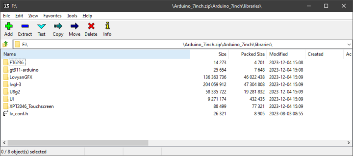
After downloading the Arduino_7inch.zip file, we need to install the necessary library manually by copying all the files in the libraries folder within Arduino_7inch to the libraries path of the Arduino IDE itself. If we are concerned that these libraries will be redundant or cause problems with the existing libraries, we can also specify the path of this library elsewhere. To do this, open the File/Preferences menu and set the Sketchbook location to the path you want.
Then, I opened the HMI-7.ino file and tried to add the command Serial.println("Yes!"); at the last line of the setup() function to check if the new code was running. Then, I tried to compile it. The first common problem I found was that the Arduino GFX library was still missing. So I installed version 1.3.1 and retried. The compilation took a moment, and although I noticed several warnings, the code compiled without any problems.
Preparing the code samples for the 3.5-inch screen
To flash the Factory Demo Code example to this screen, the process is similar to the example mentioned earlier. We need to place the board’s library into the Arduino ‘libraries’ folder. Additionally, we have to replace the User_Setup.h file of the TFT_eSPI library with the file from the downloaded firmware to ensure that the TFT_eSPI settings align with our device.
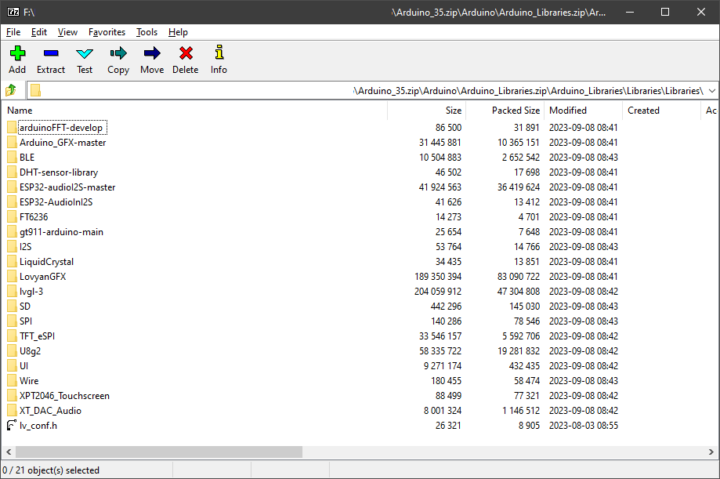
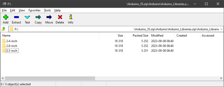
For this screen, I used the file LVGL_Arduino3.5RTP-Hor.ino from the folder 3.5-Factory-Program\3.5-Factory-Program\LVGL_Arduino3.5RTP-Hor\, extracted from the 3.5-Factory-Program.zip file. For me, the compilation was done without any additional issues.
Uploading code to Elecrow ESP32 display modules
To upload the binary to the board, you need to put the ESP32 display modules in the download mode first. You can do this by holding down the BOOT button on the board, followed by a short press of the RESET button, and then releasing the BOOT button. Once successful, the board will enter the download mode, and the screen will turn black. You can open the Serial Monitor window to check if the board has entered the download mode. The board will display the message ‘waiting for download‘ if the entry into the download mode is successful.
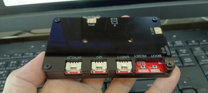
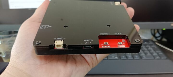
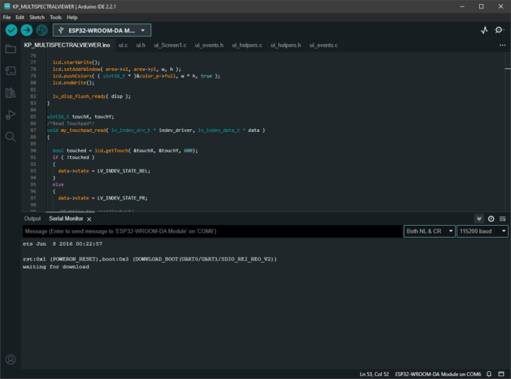
Once in the download mode, press the ‘Upload’ button in the Arduino IDE to flash the program onto the board. After successfully uploading to the board, press the RESET button on the board once more to restart. You can now use the new program as intended.
The details about my received modules during the upload process are provided below.
7.0-inch screen:
- Sketch uses 1707637 bytes (54%) of program storage space. Maximum is 3145728 bytes.
- Global variables use 94316 bytes (28%) of dynamic memory, leaving 233364 bytes for local variables. Maximum is 327680 bytes.
- Chip is ESP32-S3
- Features: WiFi, BLE
- Crystal is 40MHz
3.5-inch screen:
- Sketch uses 2375949 bytes (75%) of program storage space. Maximum is 3145728 bytes.
- Global variables use 74536 bytes (22%) of dynamic memory, leaving 253144 bytes for local variables. Maximum is 327680 bytes.
- Chip is ESP32-D0WDQ6 (revision 1)
- Features: WiFi, BT, Dual Core, 240MHz, VRef calibration in efuse, Coding Scheme None
- Crystal is 40MHz
After examining the code of the 3.5-inch display module, I found that this factory demo program has a testing mode for us to try out. To do this, we type ‘b‘ in the Serial Monitor and select the mode we want to test according to the information below. In summary, there are several test modes for various components of the board, such as typing ‘R‘ to display the screen in red, test GPIO signals, test the touchscreen, and WiFi connection, etc. Each mode provides additional information to read through the Serial Monitor, and you can exit each mode by typing the lowercase letter ‘i‘.
Here’s the list of available commands.
- R: Displays the screen in red
- G: Displays the screen in green
- B: Displays the screen in blue
- S: Tests the SD card
- T: Tests the touchscreen
- L: Tests the GPIO pins
- i: Tests the I2C interface
- W: Tests the WiFi connection
- U: Tests the serial port
- P: Tests the speaker
- V: Tests the Bluetooth connection
- I: Exits the current test mode and returns to the main menu
- C: Exits the test mode and returns to the normal screen
Example applications
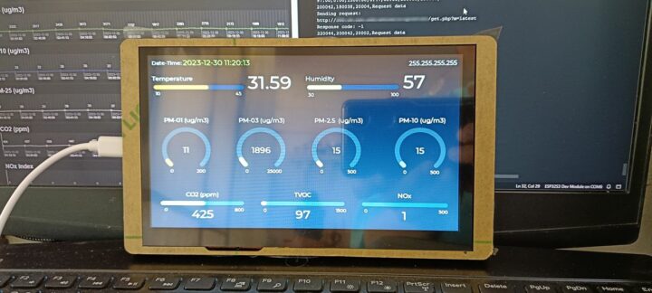
For experimenting with other components such as GPIO-D, I2C, TF, and UART-1, I tested the examples for each board and found that they worked as expected. Therefore, for the remaining part of this review, I will test the functionality by doing two mini-projects. I will use the 7.0-inch touchscreen module as a dashboard for displaying air quality data, and the 3.5-inch touchscreen module to display values obtained from a multispectrometer module through the I2C port.
Mini-project 1: Air quality dashboard with Elecrow 7-inch ESP32 display module
For the air quality data to be displayed, I will use information from the AirGradient ONE which I reviewed earlier. I made slight adjustments to the server-side code simply to support HTTP GET/POST requests for retrieving the latest measurement data and responding in JSON format. In this review, there are 11 values to be displayed, according to the JSON format below.
{"result":"OK","data":[{"id":"32403","date_time":"2023-12-31 09:36:04","tvoc":"67","nox":"2","co2":"422","pm25":"20","pm01":"12","pm10":"20","pm03pcount":"2229","temp":"29.6","hum":"62"}]}
After that, I designed the UI to display the data using SquareLine Studio version 1.3.2. In this sample program, I divided the screen into three parts. The first part is used to display the date and time. The second part displays temperature and humidity data. The third part displays the remaining data. I set the necessary values in SquareLine Studio as follows.
- Create/Arduino with TFT_eSPI
- Resolution: 800×480
- Color depth: 16-bit
- Choose LVGL version based on device’s library version: 8.3.3
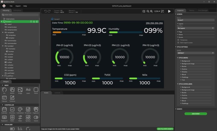
I used the 7.0-inch_Squareline_Demo.ino file from the manufacturer’s GitHub as the starting code. I added code related to the WiFi connection and used Arduino JSON version 0.2.0 to handle JSON data from the server as shown below.
|
1 2 3 4 5 6 7 8 9 10 11 12 13 14 15 16 17 18 19 20 21 22 23 24 25 26 27 28 |
void request_data() { String url = API_ENDPOINT + "/get.php?m=latest"; Serial.println("Sending request: "); Serial.println(url); http.begin(url.c_str()); http_request_payload = "api_key=KEY&m=MODE"; http.addHeader("Content-Type", "application/x-www-form-urlencoded"); http_response_code = http.POST(http_request_payload); Serial.print("Response code: "); Serial.println(http_response_code); if(http_response_code > 0){ String response_text = http.getString(); Serial.print("Response text: "); Serial.println(response_text); JSONVar my_json_obj = JSON.parse(response_text); Serial.print("Result: "); Serial.println(my_json_obj["result"]); Serial.print("data: "); Serial.println(my_json_obj["data"]); // Show the latest data show_data(my_json_obj["data"][0]); } http.end(); } |
I then updated the UI elements by using the update_arc and update_bar functions. The functions simply take the data value (val), the lower (min) and upper (max) limits, as well as the threshold value (t0, t1, t2) to determine the color for specific ranges. The input value will be scaled to 0 – 100 range and the given UI element will be updated according to the functions below.
|
1 2 3 4 5 6 7 8 9 10 11 12 13 14 15 16 17 18 19 20 21 22 23 24 25 26 27 28 |
void update_arc(lv_obj_t *arc, float val, float min, float max, float t0, float t1, float t2) { float y = 100.0 * ((val - min)/(max - min)); if(y <= 0.0) { y = 0.0; } if(y >= 100.0) { y = 100.0; } lv_arc_set_value(arc, int(y)); if((val >= min) && (val < t0)) { // Blue lv_obj_set_style_arc_color(arc, color_value_low, LV_PART_INDICATOR | LV_STATE_DEFAULT ); } else if((val >= t0) && (val < t1)) { // Green lv_obj_set_style_arc_color(arc, color_value_normal, LV_PART_INDICATOR | LV_STATE_DEFAULT ); } else if((val >= t1) && (val < t2)) { // Yellow lv_obj_set_style_arc_color(arc, color_value_high, LV_PART_INDICATOR | LV_STATE_DEFAULT ); } else if(val >= t2) { // Red lv_obj_set_style_arc_color(arc, color_value_very_high, LV_PART_INDICATOR | LV_STATE_DEFAULT ); } else { lv_obj_set_style_arc_color(arc, color_value_error, LV_PART_INDICATOR | LV_STATE_DEFAULT ); } } |
|
1 2 3 4 5 6 7 8 9 10 11 12 13 14 15 16 17 18 19 20 21 22 23 24 25 26 27 28 |
void update_bar(lv_obj_t *bar, float val, float min, float max, float t0, float t1, float t2) { float y = 100.0 * ((val - min)/(max - min)); if(y <= 0.0) { y = 0.0; } if(y >= 100.0) { y = 100.0; } lv_bar_set_value(bar, int(y), LV_ANIM_OFF); if((val >= min) && (val < t0)) { // Blue lv_obj_set_style_bg_color(bar, color_value_low, LV_PART_INDICATOR | LV_STATE_DEFAULT ); } else if((val >= t0) && (val < t1)) { // Green lv_obj_set_style_bg_color(bar, color_value_normal, LV_PART_INDICATOR | LV_STATE_DEFAULT ); } else if((val >= t1) && (val < t2)) { // Yellow lv_obj_set_style_bg_color(bar, color_value_high, LV_PART_INDICATOR | LV_STATE_DEFAULT ); } else if(val >= t2) { // Red lv_obj_set_style_bg_color(bar, color_value_very_high, LV_PART_INDICATOR | LV_STATE_DEFAULT ); } else { lv_obj_set_style_bg_color(bar, color_value_error, LV_PART_INDICATOR | LV_STATE_DEFAULT ); } } |
Mini-project 2: Multispectrometer display with Elecrow 3.5-inch ESP32 display module
I am a lecturer at a university in Thailand. We typically have courses that use multi-spectrometers to compare the reflectance of plants or other objects on the ground with values analyzed from satellite imagery. The problem is that while these devices offer high-resolution measurements, they’re often very expensive, i.e., ranging from thousands to tens of thousands of US dollars for some models. This can limit my students’ opportunities to get hands-on practice and complete data analysis.
Therefore, for the final part of this review and testing, I will experiment with the 3.5-inch display together with the Sparkfun AS7341 module (unfortunately, this module is no longer in production). The goal is to create a portable and cost-effective device for measuring values. This module is an economical multispectral sensor designed for measuring light across various wavelengths. It utilizes the AS7341 sensor from AMS, capable of measuring light in 11 wavelength ranges, covering from the blue color (415 nanometers) to the near-infrared (NIR) (915 nanometers). The module supports both Qwiic and I2C connections.
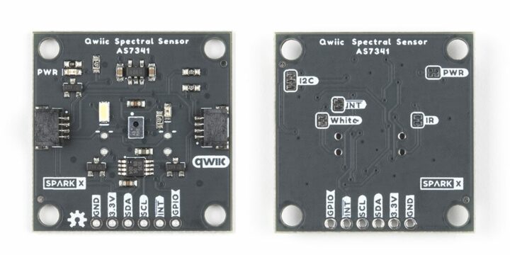
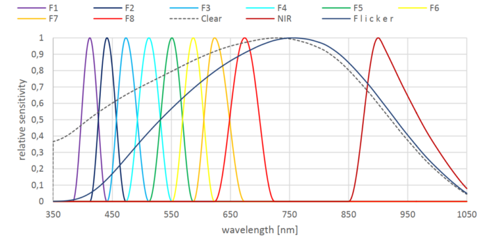
I connected the display module to the AS7341 sensor through I2C using the provided cables from the manufacturer. However, I encountered issues when trying to use the sensor with the Sparkfun AS7341X Arduino Library (which has also occurred with many ESP32 boards that I have). I then tested the connection with the Adafruit AS7341 Arduino Library, which is designed for a different module but uses the same AS7341 sensor. Using the library from the Adafruit, I can connect to the sensor. Even though I cannot control the white, NIR, and UV LEDs on the sensor module, but I can call the functions to test the scan successfully. So, I will use the library from Adafruit to demonstrate the application.
A minor issue I found at this step is that the I2C pins on the received display module are set as SDA = 22 and SCL = 21, which might be confused with the typical configuration of other ESP32 boards whereSDA is often set as 21 and SCL as 22. To address this, I simply adjusted the Wire.begin() call by adding the correct pin numbers as parameters.

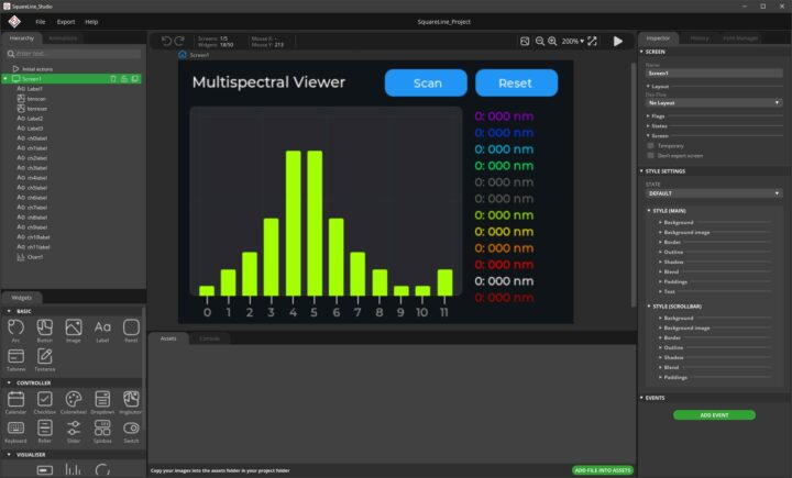
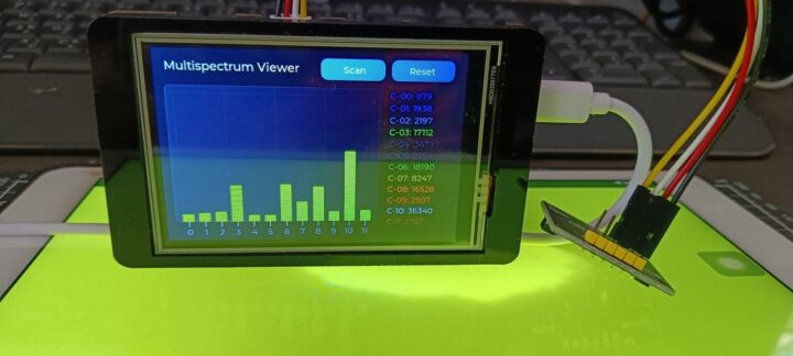
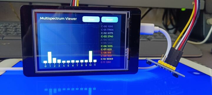
In this demonstration, I will simply read the light values from the sensor without performing any calibration. The values obtained from the sensor will be in the form of uint16_t, acquired using the readAllChannels() function, and then passed to another function to update UI elements. The UI was designed using SquareLine Studio version 1.3.2, displaying both bar graphs and text. However, since the data in channels C4 (clear) and C5 (NIR) are repeated with channels C10 (clear) and C11 (NIR), my program will not display the values of C4 and C5 in the graph but will still show them in labels, as shown in the design example below.
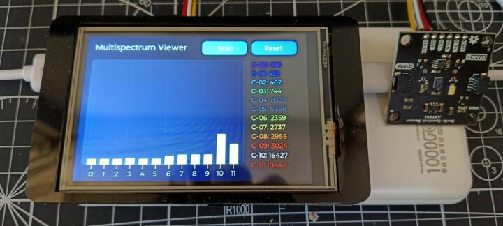
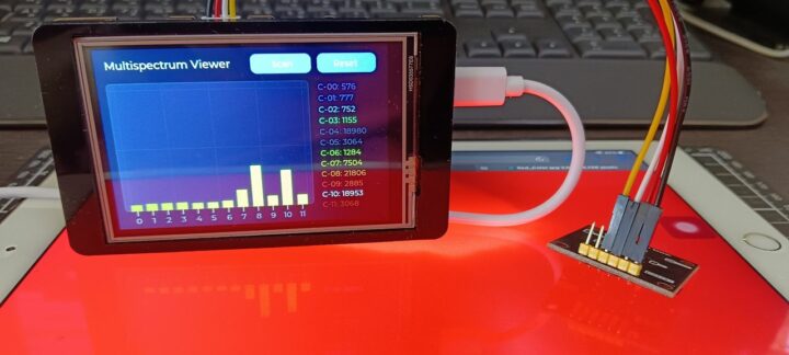
The final part was adding code to save the scanning results as a CSV file for further use. Using the SD card is also convenient and there are no problems. However, we need to make sure that the touch device is stopped during SD card usage. After writing the file, we can resume touch device functionality. In addition, I have added the use of the GPIO-25 pin to toggle an external LED during scanning. The results are shown in the example images below.
Others
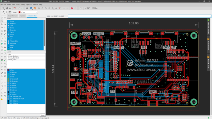
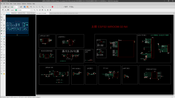
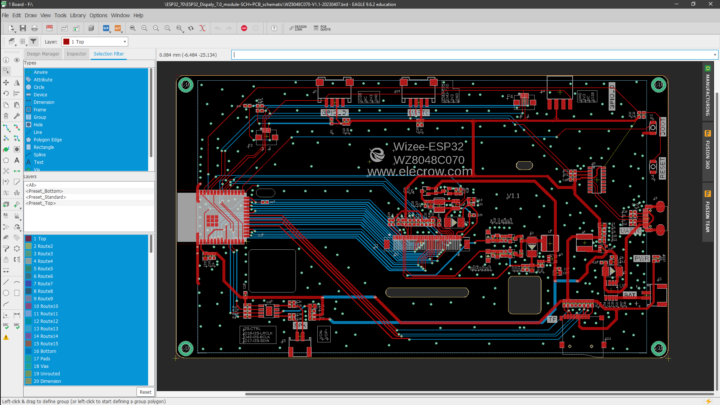
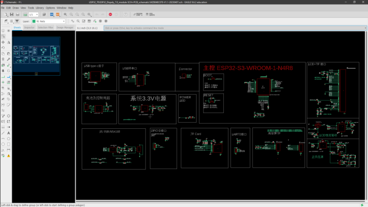
Elecrow is an open-source hardware manufacturer. In addition to the various source codes mentioned above, the manufacturer also provides PCB and schematic diagram files for us to study and develop further. Anyone interested in learning more about the circuits can open and view the PCB and schematic diagram files for the 3.5-inch and 7-inch screens in the SCH+PCB folder in the aforelinked GitHub repository. I can open them with Autodesk EAGLE 9.6.2 Education License without any problems.
Conclusion
In summary, both sets of screens work well. Programming with Arduino IDE is also convenient because the libraries provided are quite complete and can be used immediately without having to adjust the version. The screens are also bright and colorful as usual for TFT LCD screens. Personally, I would like to add one more GPIO or SPI port to support more functionality. For the 3.5-inch display, entering the download mode by pressing the RESET and the BOOT buttons can be done with one hand, but it may not be very convenient because the case slots around the two buttons are a bit too narrow (or maybe my fingers are too fat, I’m not sure).
Actually, in this review, I intended to use both screens together with the SONY Spresense board to display various information from the Japanese Quasi-Zenith Satellite System (QZSS), which is a global navigation satellite system, similar to the Global Positioning System (GPS) of the United States. I also planned to showcase emergency alert data that is embedded in the QZSS satellite signals on the screens. However, due to time constraints, I will separate the usage of the screens with the SONY Spresense into another article.
Finally, I would like to say thank you to Elecrow for providing me with the ESP32 3.5-inch HMI Display and ESP32 7.0-inch HMI Display for testing. If anyone is interested, they can purchase directly from the manufacturer and as of now, the 3.5-inch screen reviewed here with acrylic case is priced at 20.63 USD, and the 7.0-inch screen sells for 34.53 USD.

My main research areas are digital image/audio processing, digital photogrammetry, AI, IoT, and UAV. I am open to other subjects as well.
Support CNX Software! Donate via cryptocurrencies, become a Patron on Patreon, or purchase goods on Amazon or Aliexpress


