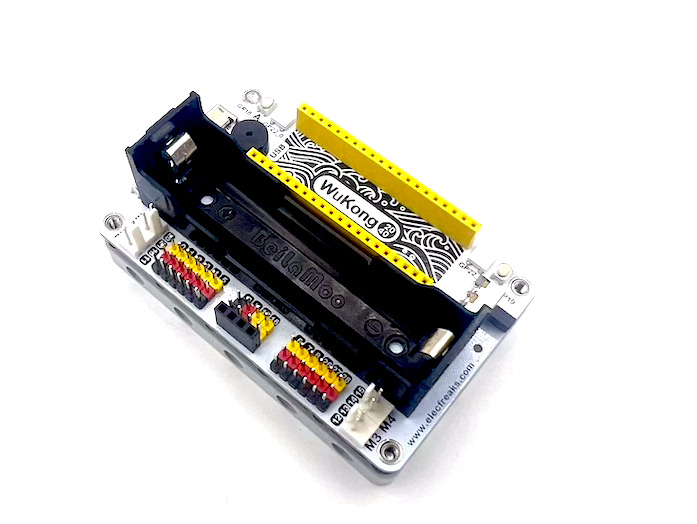
ELECFREAKS Wukong 2040 is a multifunctional breakout board designed for Raspberry Pi Pico. It is equipped with interfaces for four DC motors, up to twelve servos, a buzzer, A\B buttons, RGB “rainbow” lights, a Reset button, etc… The board can be powered by a single 18650 3.7V LiPo battery and integrates a power management IC that monitors the battery level and can also charge the battery via a USB charger. Battery life is typically 60 minutes per charge but can last over 120 minutes depending on the load.
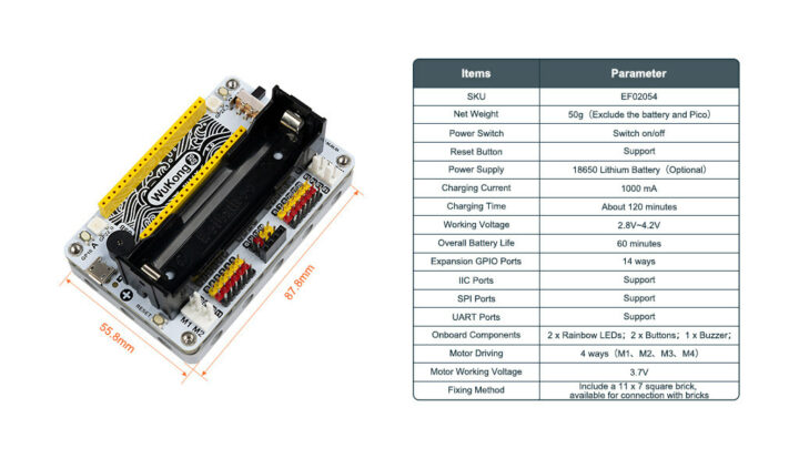
Wukong 2040 key features and specifications
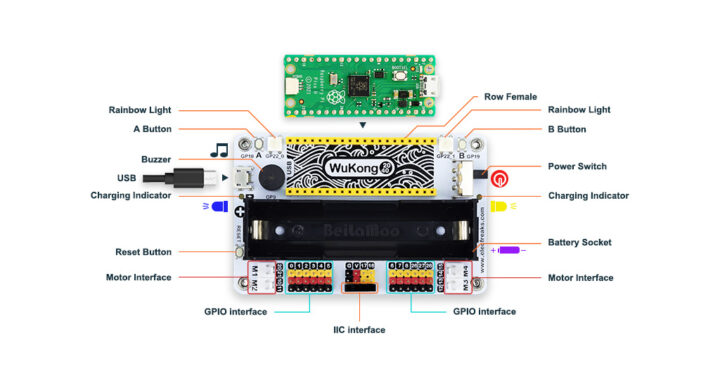
Description of the Wukong 2040 interfaces
Specifications and dimensions of the Wukong 2040 Expansion Board for Raspberry Pi Pico
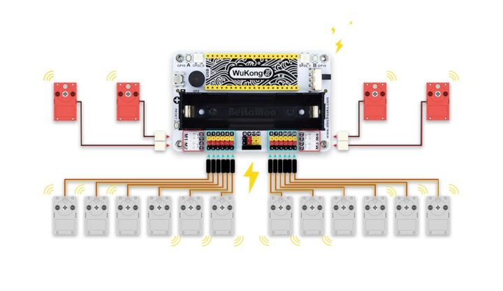
 The Wukong 2040 breakout board for the Raspberry Pi Pico can control up to four DC motors and up to 12 servo motors as shown in the diagram below.
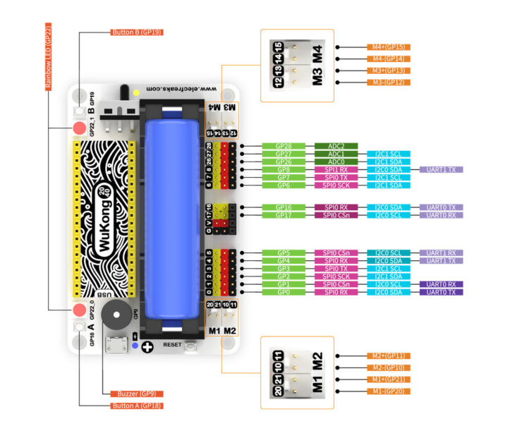
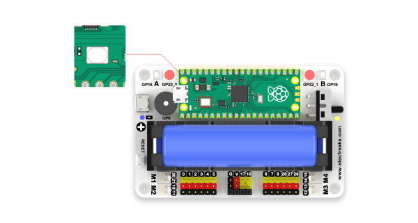
 Pinout diagram of the Wukong 2040 board
Getting started with the Wukong 2040 and Raspberry Pi Pico using CircuitPython
Board and host preparation
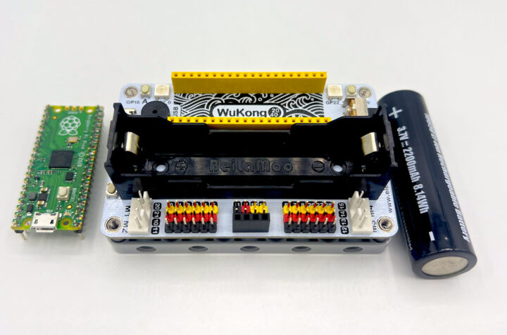
The Wukong 2040 breakout board can be used with the Raspberry Pi Pico, which we’ll use here, or the Raspberry Pi Pico W board, and uses one 18650 battery for power. We went with 2,200mAh battery for this tutorial/review.
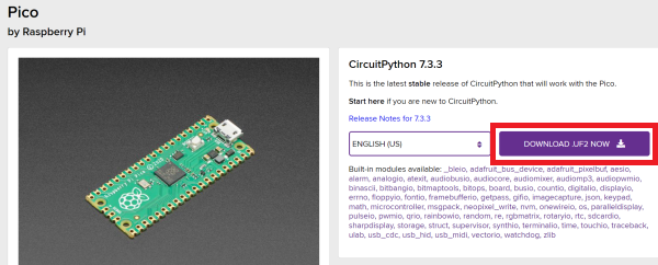
The Raspberry Pi Pico board supports C/C++, MicroPython, CircuitPython, and other programming languages. We’ll go with CircuitPython as it is an easy-to-use programming language and we can download the UF2 firmware from the official website.
Once we have downloaded the firmware, we can press and hold the BOOTSEL button to enter flashing mode.
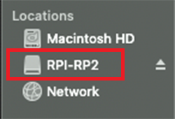
 Then we can connect the Raspberry Pi Pico to the computer using a USB cable and release the BOOSEL button on the Raspberry Pi Pico board. The board should show up as “RPI-RP2” drive.
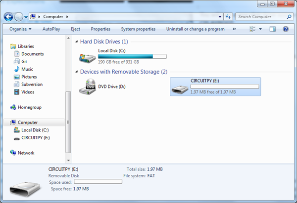
Now drag the previously downloaded UF2 file to the “RPI-RP2” drive and once the installation is complete, the “RPI-RP2” drive will disappear and the “CIRCUITPY” drive will appear in its place. That means we have successfully installed the CircuitPython firmware.
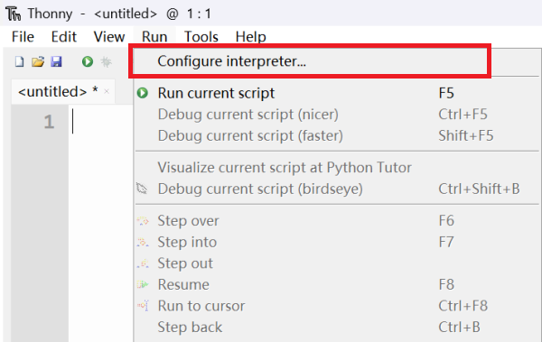
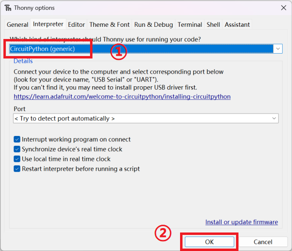
We’ll use the Thonny Python IDE for programming which can install on Windows, Linux, macOS, or even run from a Raspberry Pi SBC. Once the installation is complete, open Thonny, then click on the “Run” menu and select “Configure interperter”.
In the “Interperter” window:
- Click to select “CircuitPython(generic)”
- Click “OK” to complete the setup.
Using the A and B buttons on the Wukong 2040
Now that your board and host computer are ready we can start programming the board. We’ll start with the buttons. Push button A is connected to GPIO 18 of the Raspberry Pi Pico board and Push button B is connected to GPIO 19.
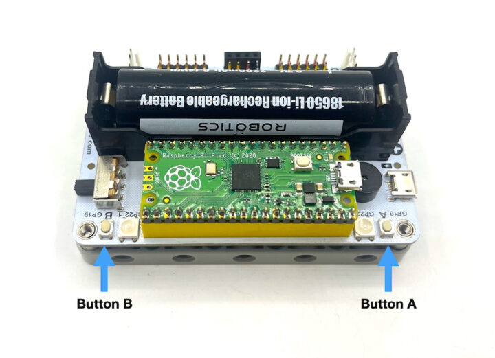 The code sample below if the A button is pressed, the LED on the Raspberry Pi Pico board will turn on, or if the B button is pressed, the LED on the Raspberry Pi Pico board will turn off.
|
1 2 3 4 5 6 7 8 9 10 11 12 13 14 15 16 17 18 19 20 |
import board import digitalio led_onboard = digitalio.DigitalInOut(board.LED) led_onboard.direction = digitalio.Direction.OUTPUT button_a = digitalio.DigitalInOut(board.GP18) # Create the wukong2040 button A object from the pins button_b = digitalio.DigitalInOut(board.GP19) button_a.direction = digitalio.Direction.INPUT # Set button_a to output mode button_b.direction = digitalio.Direction.INPUT button_a.pull = digitalio.Pull.UP # Set the pull-up button_b.pull = digitalio.Pull.UP while True: if button_a.value == False: # The value of button_a.value is the status value of button A. Pressing is 0, releasing is 1. led_onboard.value = True elif button_b.value == False: # The value of button_b.value is the status value of button B. Pressing is 0, releasing is 1. led_onboard.value = False |
Programming the buzzer
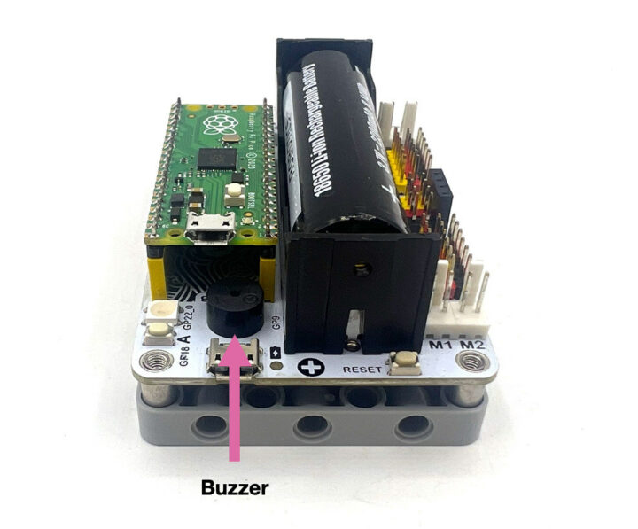
Let’s now play with the buzzer connected to GPIO 9
The code below generates a sine wave to play sound through the buzzer after button A is pressed:
|
1 2 3 4 5 6 7 8 9 10 11 12 13 14 15 16 17 18 19 20 21 22 23 24 25 26 27 28 29 30 31 32 33 |
import time import array import math import board import digitalio from audiocore import RawSample try: from audioio import AudioOut except ImportError: try: from audiopwmio import PWMAudioOut as AudioOut except ImportError: pass button = digitalio.DigitalInOut(board.GP18) button.switch_to_input(pull=digitalio.Pull.UP) tone_volume = 0.9 frequency = 440 length = 8000 // frequency sine_wave = array.array("H", [0] * length) for i in range(length): sine_wave[i] = int((1 + math.sin(math.pi * 2 * i / length)) * tone_volume * (2 ** 15 - 1)) audio = AudioOut(board.GP9) sine_wave_sample = RawSample(sine_wave) while True: if not button.value: audio.play(sine_wave_sample, loop=True) time.sleep(1) audio.stop() |
Wukong 2040 RGB LED control
The Wukong 2040 board also comes with two RGB LED (WS2812B) connected to GPIO 22 of the Raspberry Pi Pico board.
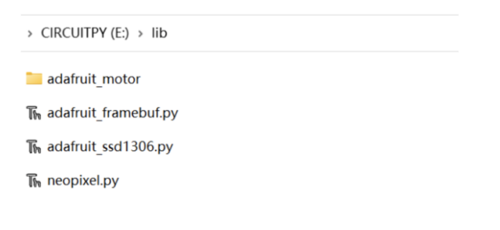
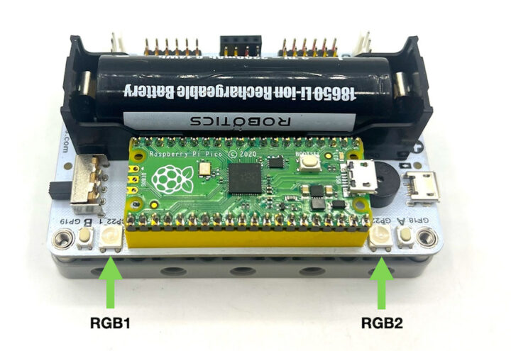 We’ll use Adafruit’s Neopixel library to program the RGB LED with CircuitPython. Once the neopixel.py library is downloaded, we can copy it to the “lib” directory of the “CIRCUITPY” drive.
![]() The code below changes the color of the two RGB lights in an infinite loop.
The code below changes the color of the two RGB lights in an infinite loop.
|
1 2 3 4 5 6 7 8 9 10 11 12 13 14 15 16 17 18 19 20 21 22 |
import time import board from rainbowio import colorwheel import neopixel NUMPIXELS = 2 SPEED = 0.05 BRIGHTNESS = 0.2 # Values in (0.0, 1.0), where 0.0 is off and 1.0 is maximum PIN = board.GP22 # Rainbow bead pins are GP22 pixels = neopixel.NeoPixel(PIN, NUMPIXELS, brightness=BRIGHTNESS, auto_write=False) def rainbow_cycle(wait): for color in range(255): for pixel in range(len(pixels)): pixel_index = (pixel * 256 // len(pixels)) + color * 5 pixels[pixel] = colorwheel(pixel_index & 255) pixels.show() time.sleep(wait) while True: rainbow_cycle(SPEED) |
DC motor control test with Raspberry Pi Pico and Wukong 2040
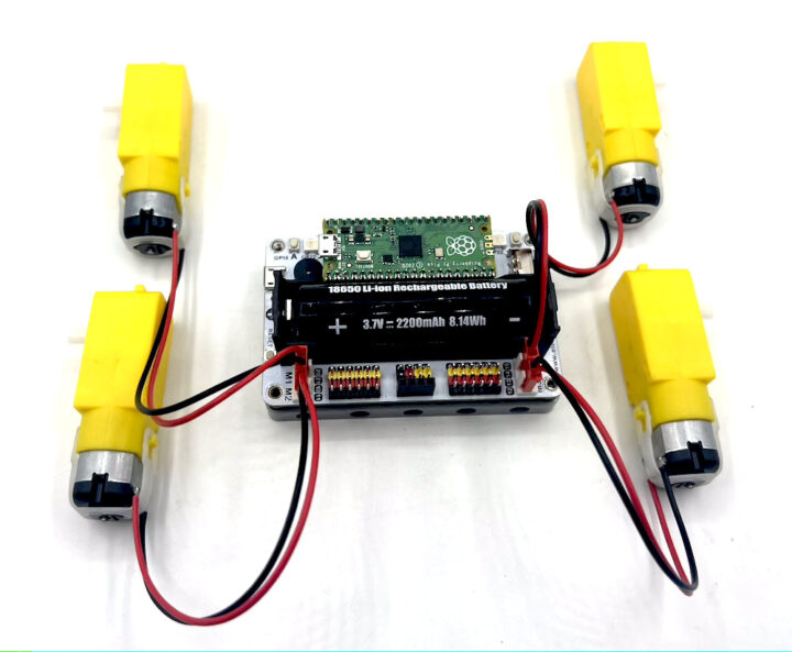
Let’s now connect four DC motors to the M1-4 ports of the Wukong 2040 which are themselves wired to the Raspberry Pi Pico as follows:
- Port M1 is connected to GPIO20 and GPIO21
- Port M2 is connected to GPIO10 and GPIO11
- Port M3 is connected to GPIO12 and GPIO13
- Port M4 is connected to GPIO14 and GPIO15
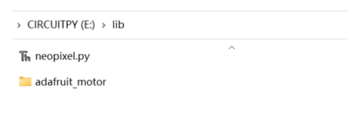
We’ll need another library to program the DC motor controller with CircuitPython: adafruit_motor. Copy the adafruit_motor folder to the “lib” directory of the “CIRCUITPY” drive.
 The motor control code sample for Raspberry Pi Pico below sets the speed of the four DC motors by adjusting the frequency of the pulse signal (PWM). We can create basic movement functions of motor rotation, forward, backward, left turn, right turn, motor stop, etc… The test program instructs the motors to go forward for 5 seconds, then stop all motors for 1 second, then reverse for 5 seconds, then stop all motors for 1 second, and so on in an infinite loop.
|
1 2 3 4 5 6 7 8 9 10 11 12 13 14 15 16 17 18 19 20 21 22 23 24 25 26 27 28 29 30 31 32 33 34 35 36 37 38 39 40 41 42 43 44 45 46 47 48 49 50 51 52 53 54 55 56 57 58 59 60 61 62 63 64 65 66 67 68 69 70 71 72 73 74 |
import board import digitalio import time import pwmio from adafruit_motor import motor motor1A = board.GP20 motor1B = board.GP21 motor2A = board.GP10 motor2B = board.GP11 motor3A = board.GP12 motor3B = board.GP13 motor4A = board.GP14 motor3B = board.GP15 pwm1A = pwmio.PWMOut(motor1A, frequency=50) pwm1B = pwmio.PWMOut(motor1B, frequency=50) pwm2A = pwmio.PWMOut(motor2A, frequency=50) pwm2B = pwmio.PWMOut(motor2B, frequency=50) pwm3A = pwmio.PWMOut(motor3A, frequency=50) pwm3B = pwmio.PWMOut(motor3B, frequency=50) pwm4A = pwmio.PWMOut(motor4A, frequency=50) pwm4B = pwmio.PWMOut(motor4B, frequency=50) motor1 = motor.DCMotor(pwm1A, pwm1B) motor2 = motor.DCMotor(pwm2A, pwm2B) motor3 = motor.DCMotor(pwm3A, pwm3B) motor4 = motor.DCMotor(pwm4A, pwm4B) def forward(speedM): motor1.throttle = speedM motor2.throttle = speedM motor3.throttle = speedM motor4.throttle = speedM def backward(speedM): motor1.throttle = -speedM motor2.throttle = -speedM motor3.throttle = -speedM motor4.throttle = -speedM def turnLeft(speedM): #max = 1 motor1.throttle = -speedM motor2.throttle = -speedM motor3.throttle = speedM motor4.throttle = speedM def turnRight(speedM): #max = 1 motor1.throttle = speedM motor2.throttle = speedM motor3.throttle = -speedM motor4.throttle = -speedM def stopall(): motor1.throttle = 0 motor2.throttle = 0 motor3.throttle = 0 motor4.throttle = 0 while True: forward(0.8) time.sleep(5) stopall() time.sleep(1) backward(0.8) time.sleep(5) stopall() time.sleep(1) |
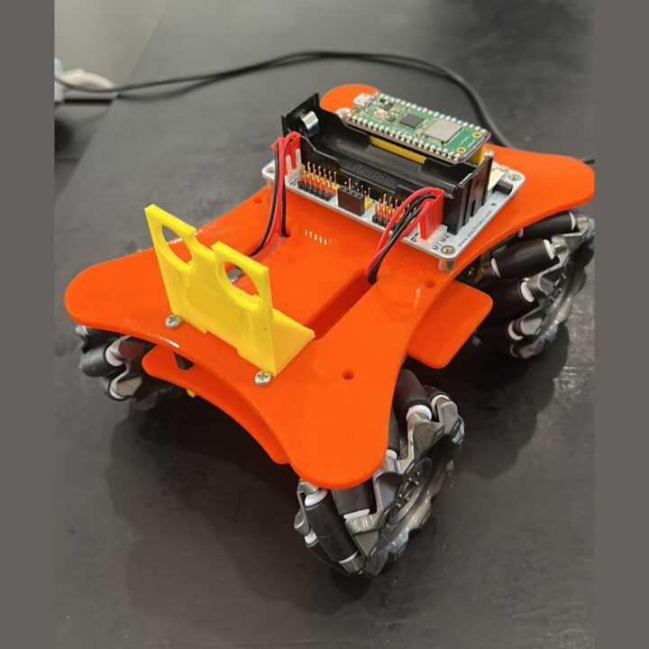
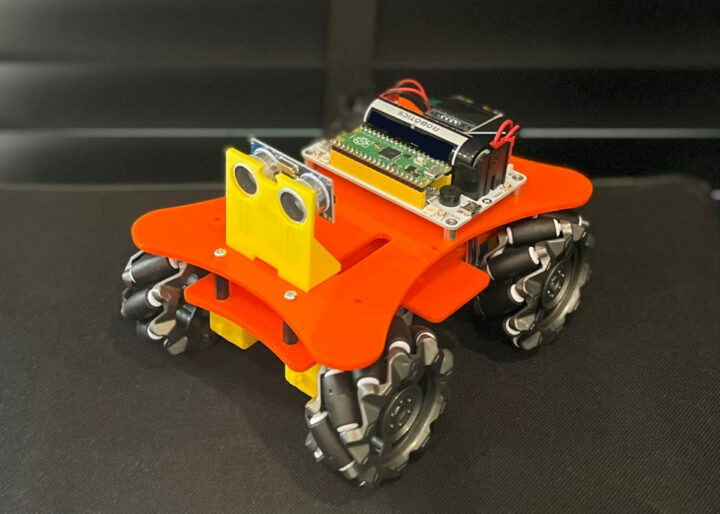
The board can also be installed into a proper robot with four wheels such as the mecanum wheel-powered robot shown below.
Raspberry Pi Pico Servo control with CircuitPython
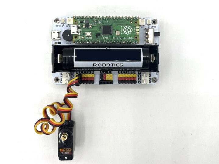
There are 12 input/output interfaces on the Wukong 2040 board (GPIO: 0, 1, 2, 3, 4, 5, 6, 7, 8, 26, 27, 28), which can be used to drive small servos. In this experiment, we will connect one servo motor to channel 0.
The test program below makes the servo motor rotates from 0 degrees to 180 degrees, and then from 180 degrees to 0, repeating the cycle in an infinite loop.
|
1 2 3 4 5 6 7 8 9 10 11 12 13 14 15 16 |
import time import board import pwmio from adafruit_motor import servo pwm = pwmio.PWMOut(board.GP0, duty_cycle=2 ** 15, frequency=50) my_servo = servo.Servo(pwm) while True: for angle in range(0, 180, 5): my_servo.angle = angle time.sleep(0.05) for angle in range(180, 0, -5): my_servo.angle = angle time.sleep(0.05) |
Driving an I2C OLED display with CircuitPython
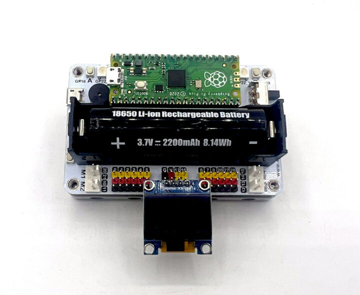
The Wukong 2040 breakout board for Raspberry Pi Pico has a built-in I2C interface (GP16, GP17) that can drive an OLED display, and we’ll use one with 128×64 resolution in this review.
In order to program an OLED display with CircuitPython we’ll use two more libraries from Adafruit: adafruit_ssd1306.py and adafruit_framebuf.py. Copy both files to the “lib” directory in the “CIRCUITPY” drive.
The code sample below fills the screen, then draws a horizontal line, a vertical line, a circle, and a square to the OLED:
|
1 2 3 4 5 6 7 8 9 10 11 12 13 14 15 16 17 18 19 20 21 22 23 24 25 26 27 28 29 30 31 32 33 34 35 36 37 38 39 40 41 42 43 44 45 46 47 48 |
import board import busio import adafruit_ssd1306 import time i2c = busio.I2C(board.GP17, board.GP16) display = adafruit_ssd1306.SSD1306_I2C(128, 64, i2c, addr=0x3C) bgColor=0 display.fill(bgColor) for i in range(0,display.height,4): for j in range(0,display.width,4): display.pixel(j, i, not bgColor) display.show() display.fill(bgColor) for i in range(0,display.height,4): display.hline(0, i,display.width, not bgColor) display.show() display.fill(bgColor) for i in range(0,display.width,8): display.vline(i, 0,display.height, not bgColor) display.show() display.fill(bgColor) for i in range(0,display.height,4): display.line(0, 0, display.width, i, not bgColor) display.line(display.width, display.height, 0, display.height-i, not bgColor) display.show() display.fill(bgColor) for i in range(0,display.width//2,4): display.circle(display.width//2, display.height//2, i, not bgColor) display.show() display.fill(bgColor) for i in range(0,display.height,16): for j in range(0,display.width,16): display.rect(j, i, 12, 12, not bgColor) display.show() for i in range(0,display.height,16): for j in range(0,display.width,16): display.fill_rect(j+2, i+2, 8, 8, not bgColor) display.show() display.fill(bgColor) |
Conclusion
The Wukong 2040 breakout board for Raspberry Pi Pico can be used to extend the capabilities of the Pico board with the DC motor and servo control connection especially interesting to build robots such as a mecanum wheel-powered robot. While the Wukong 2040 Breakout Board for Raspberry Pi Pico can be programmed with many languages, CircuitPython based on the Python language is easy to use. The included 18650 battery holder also makes it convenient for powering your project, and the ability to charge the battery directly from the Wukong 2040 is also a plus.
I would like to thank ELECFREAKS for sending us the Wukong 2040 breakout board for Raspberry Pi Pico. It can be purchased for $9.90 on ELECFREAKS store.
This tutorial is a translation of the original review on CNX Software Thailand.

Jean-Luc started CNX Software in 2010 as a part-time endeavor, before quitting his job as a software engineering manager, and starting to write daily news, and reviews full time later in 2011.
Support CNX Software! Donate via cryptocurrencies, become a Patron on Patreon, or purchase goods on Amazon or Aliexpress


