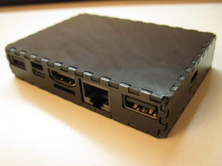
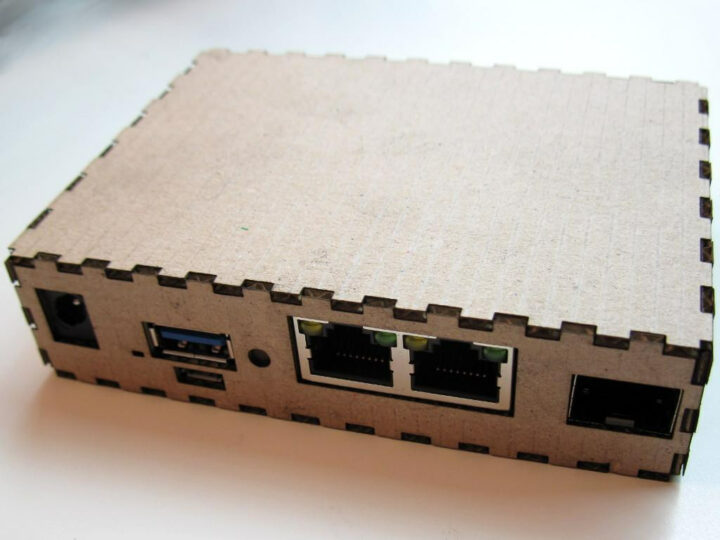
Since you can’t always rely on single board computer (SBC) vendors to provide a case to match your needs, some went the DIY route. Willy Tarreau designed some laser-cut enclosures with Inkscape for various SBCs, while hominoids went a step further by developing the “SBC Case Builder” tool to automatically generate various types of 3D printable enclosures using OpenSCAD.
Willy designed five similar enclosures for Khadas VIM3/VIM3L, FriendlyELEC NanoPi Fire3, SolidRun Clearfog Base networking SBC, Libre Computer AML-S805X-AC (aka “La Frite”), and AAEON UP Board.


All cases are available in Inkscape SVG format, and Willy accepts contributions for other boards. You’ll need a laser engraver or CNC router to cut out those enclosures.
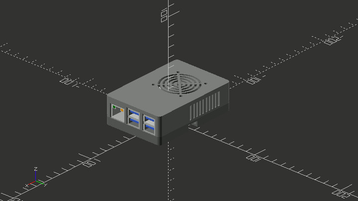
Hominoids’ SBC Case Builder project attempt to automatize enclosure generation for SBCs using SBC Model Framework written in OpenSCAD. Work has focused on ODROID boards so far, but it should work for other vendors too. The parameters are defined in a configuration file:
|
1 2 3 4 5 6 7 8 9 10 11 12 13 14 15 16 17 18 19 20 21 22 23 24 25 26 27 28 29 |
view = "model"; // viewing mode "platter", "model", "debug" case_design = "tray"; // "shell", "panel", "stacked", "tray" case_style = "vu5"; // style of case_design // tray: none, vu5 sbc_model = "c4"; // any sbc from sbc model framework: "c1+","c2","c4","hc4" // "xu4","xu4q","mc1","hc1","n1","n2","n2+","h2" pcb_loc_x = 5; // sbc location x axis pcb_loc_y = 0; // sbc location y axis case_offset_x = 0; // additional case x axis size case_offset_y = 0; // additional case y axis size case_offset_tz = 0; // additional case top z axis size case_offset_bz = 4; // additional case bottom z axis size wallthick = 2; // case wall thickness floorthick = 2; // case floor thickness sidethick = 3; // case side thickness gap = 1.5; // distance between pcb and case indents = true; // indentations around io openings sidewall_support = true; // enable wall support for standoffs sbc_top_standoffs = false; // enable sbc top standoffs sbc_bottom_standoffs = true; // enable sbc bottom standoffs case_ext_standoffs = false; // enable case extended standoffs sata_punchout = true; // enable sata punchout gpio_opening = "none"; // gpio openings "none","vent","open","punchout" cooling = "fan"; // "none", "vents", "fan", "custom" using ./dxf/customfan.dxf exhaust_vents = "vent"; // exhaust vents "none","vent" fillet = 0; // edge fillets |
This allows you to select the thickness of the walls, opening for the GPIO header, type of cooling, and other parameters to create a custom enclosure. The tool will also validated the design to make sure the board can indeed fit inside.
Once the files have been generated, the design can be 3D printed. Alternatively, it might also be possible to use a CNC machine:
I believe most if not all of them can be cut on a 3-axis CNC, maybe even on a 2 ½ axis CNC. The flat ones are doable and the others might need multiple setups but should also work, imo. I’m somewhat limited in my design because they are being produced for a 3D printer so having a mill should expand what you could do and open up better aesthetic design choices too, imo.
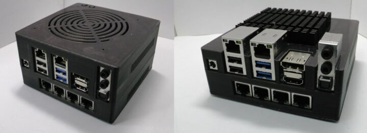
Here are some of the 3D printed enclosures created with SBC Case Builder utility.


More details can be found on odroid forum. There may be a steep learning curve before being able to use to tool to good effect since there are so many options, and models would have to be created for other single board computers.

Jean-Luc started CNX Software in 2010 as a part-time endeavor, before quitting his job as a software engineering manager, and starting to write daily news, and reviews full time later in 2011.
Support CNX Software! Donate via cryptocurrencies, become a Patron on Patreon, or purchase goods on Amazon or Aliexpress


