We’ve already seen Raspberry Pi RP2040 MCU can support VGA output using the microcontroller’s programmable I/O blocks. But yesterday, I saw two upcoming RP2040 boards with an HDMI connector. How is that supposed to work?
The first one is Olimex RP2040-PICO-PC that’s indeed like a pico PC board with an HDMI connector for video, a micro SD card for storage, a standard 3.5mm audio jack for speaker or headphone, and a USB host for a keyboard.
RP2040-PICO-PC teaser small PC with RP2040-PICO module. Video, Audio, SD-card, UEXT, I2C, Lipo battery, Reset, USB pwr, USB host for keyboard, Debug TxRx, SWD for JTAG debug #rp2040 #raspberrypi #circuitpython #retrogames pic.twitter.com/str79xsMkm
— OLIMEX Ltd (@Olimex) March 1, 2021
There are some I/O headers for good measure, what looks like a 3-pin UART console header, a 2-pin header for LiPo battery, as well as a reset button.
The second board, dcelectr DC2040, follows the Raspberry Pi Zero form factor with a 40-pin GPIO header, micro USB port, Micro SD card socket, as well as a mini HDMI port that will be used as DVI output…
I am making progress on my Pi Zero form factor board (named DC2040) with an RP2040 chip (thank you @EbenUpton). It has a mini HD.. [coughing] …a mini * port for DVI (thank you @wren6991). I will share the #KiCad files on github when the design is complete. pic.twitter.com/550PzLHrlC
— dcelectr (@dcelectr) March 1, 2021
So that’s how it works since DVI signals can be carried over an HDMI cable. The boards will transmit RGB signals without any audio since it’s not supported over DVI.
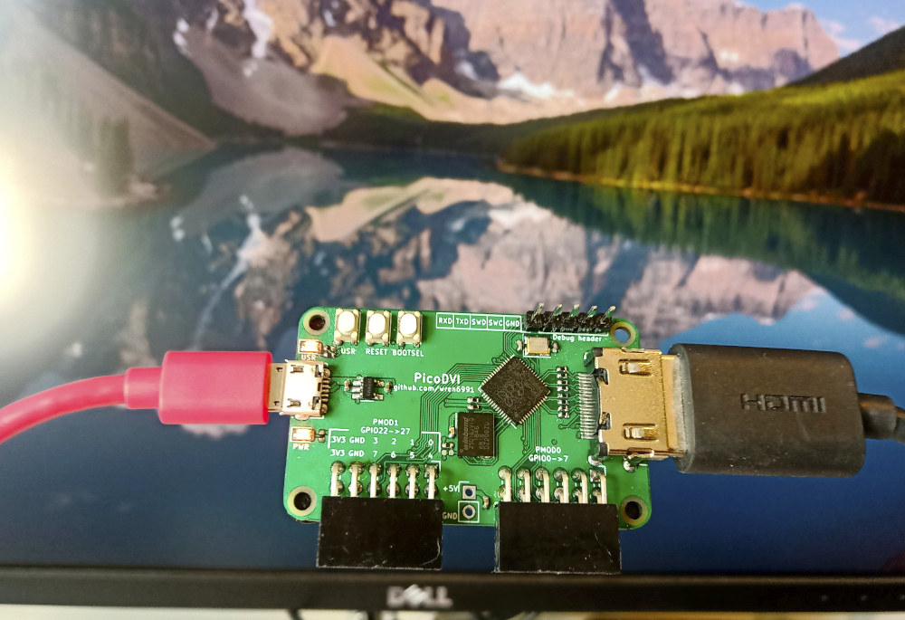
The HDMI/DVI idea appears to be derived from Raspberry Pi engineer Luke Wren (Wren6991)’s work on his PicoDVI board outputting 640x480p 60 Hz DVI mode with 264 kB SRAM used, the two Cortex-M0+ clocked at 252 MHz (that’s a bit higher than the 133 MHz advertised by the Raspberry Pi Foundation), and of course, one of the PIO blocks from Raspberry Pi RP2040 microcontroller.
Here are the resources used for one display:
- 3 out of 8 PIO state machines (the DVI code requires these all be on the same PIO instance)
- 6 out of 12 DMA channels (two per TMDS lane: one for control blocks, one for data)
- 30% of DMA bandwidth and PIO bus endpoint bandwidth
- 60% of CPU cycles on one core, other core 100% free
- Just over 50% of RAM with a QVGA RGB565 image (but RGB332 support is simple enough)
Why mentioning with one display? Because it works with two monitors as well since only one of the PIO blocks is used, half of the DMA channels are still available, and one Cortex-M0+ is still free.
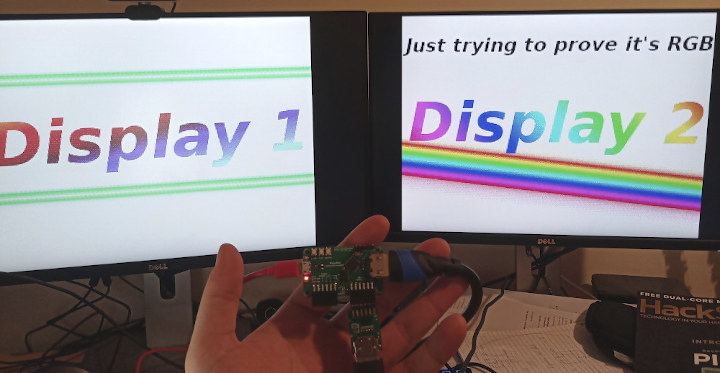
That’s pretty neat as a demo, but it’s close to reaching the limit of the Raspberry Pi RP2040 microcontroller which also had to be overclocked for the occasion. But some applications possible with one display include playing retro games, potentially programming the board directly using MicroPython or CircuitPython with the display attached, simple signage to display text and images, etc…
The hardware design files and C firmware for PicoDVI project can be found on Github together with a thorough explanation of how this all works.

Jean-Luc started CNX Software in 2010 as a part-time endeavor, before quitting his job as a software engineering manager, and starting to write daily news, and reviews full time later in 2011.
Support CNX Software! Donate via cryptocurrencies, become a Patron on Patreon, or purchase goods on Amazon or Aliexpress