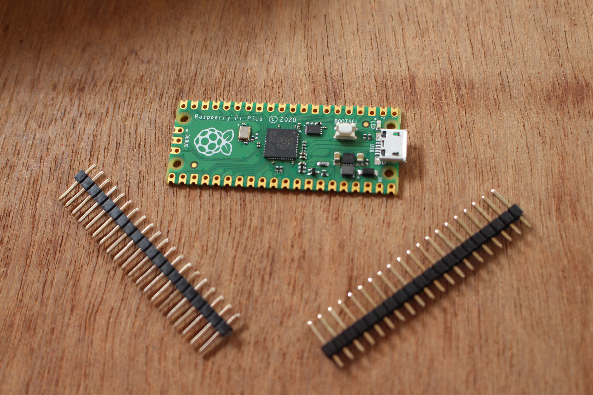
Raspberry Pi Pico board was just launched last Thursday, but thanks to Cytron I received a sample a few hours after the announcement, and I’ve now had time to play with the board using MicroPython and C programming language.
I went to the official documentation to get started, but I had to look around to achieve what I wanted to do, namely blinking some LEDs, so I’ll document my experience with my own getting started guide for Raspberry Pi Pico using a computer running Ubuntu 20.04 operating system. The instructions will be similar for Windows and Mac OS.
Preparing the hardware
In theory, we could just get started with the board alone, but since I got some headers with my board, I also took the opportunity to try out Pine64 Pinecil soldering iron powered by MINIX NEO P2 USB-C power supply.
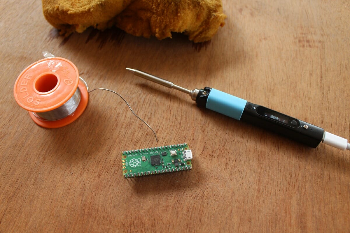
The soldering iron worked great for about one minute, and then I started to have problems with soldering… Looking a the screen I could see Zzzz and the temperature dropped. I did not move the soldering enough so it failed to detect any activity and entered into sleep. Changing the motion sensitivity or sleep timeout can easily fix this issue, and I could complete the task at hand.
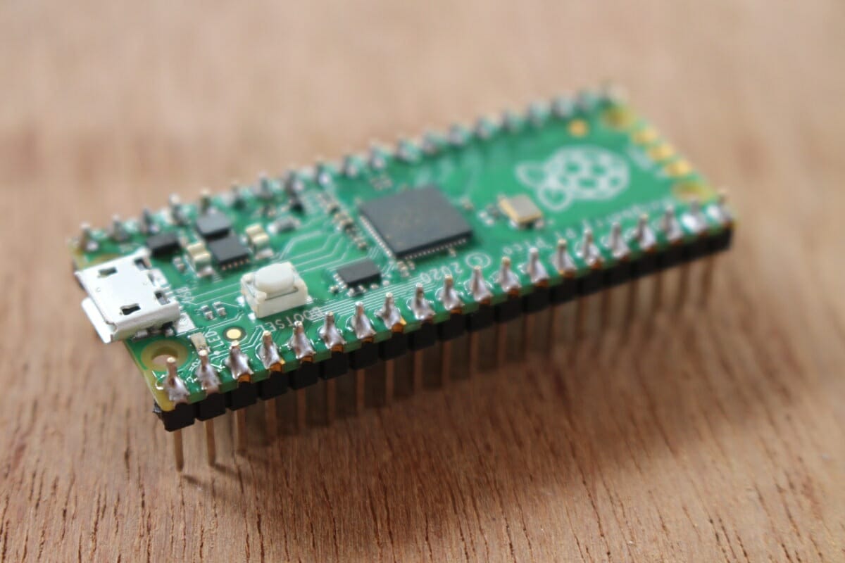
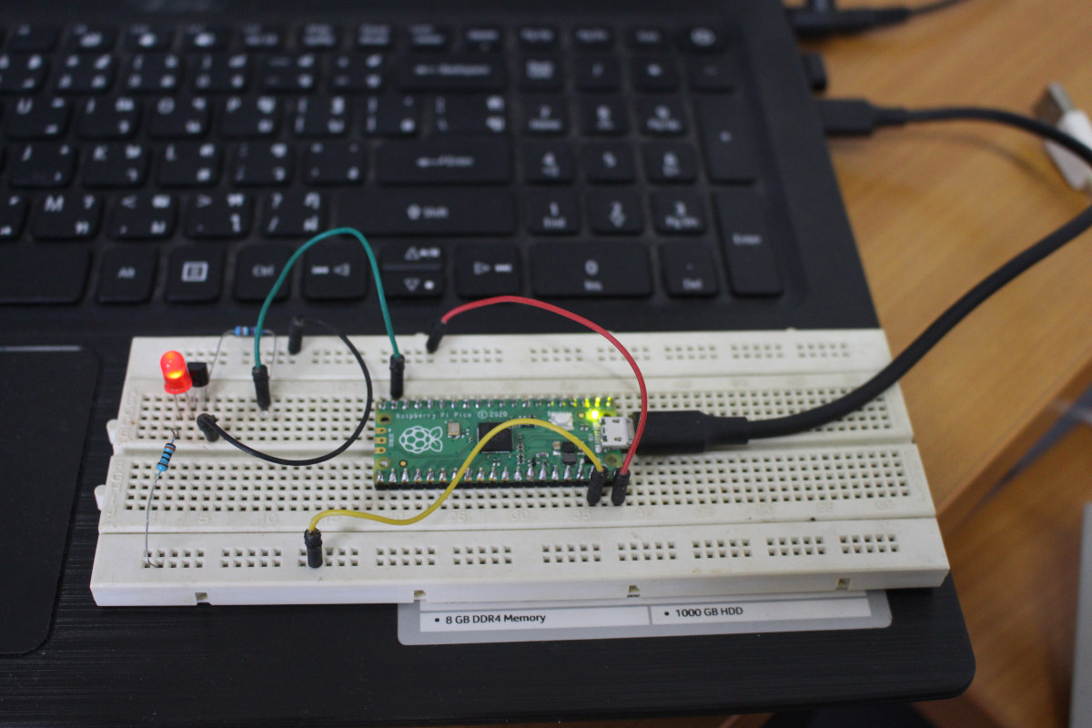
It would be a shame not to use those headers so I inserted Raspberry Pi Pico into a breadboard and added an LED with the accompanying circuitry.
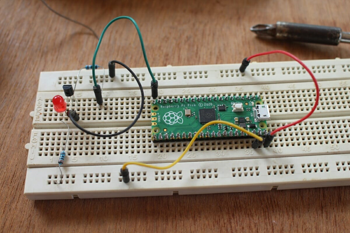
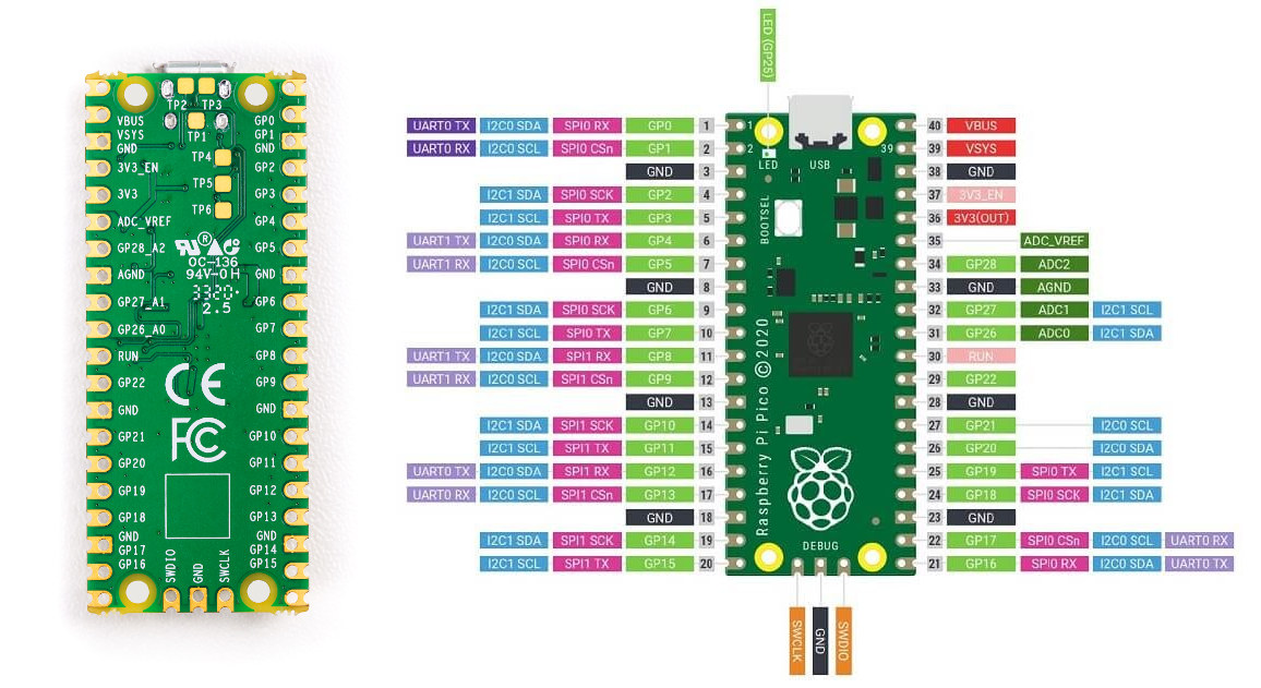
5V is connected to VBUS (pin 40), GND to pin 38, and I decide to use the GPIO the closest to the LED namely GP15 (pin 20). The GPIO markings on Raspberry Pi Pico are only shown on the bottom of the board, so when the board is connected to a breadboard a pinout diagram helps.
MicroPython on Raspberry Pi Pico
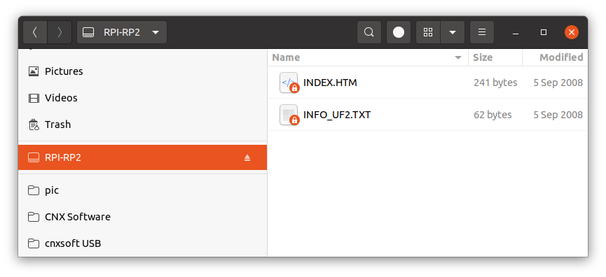
We should first copy MicroPython firmware to the board. To do so we can download the latest firmware from the getting started guide (pico_micropython_20210121.uf2 at the time of the review), then press the BOOTSEL key on the board while connecting to a computer with a USB port, and release the key after connection. I did so, but nothing happened. That’s because I used my bicycle headlight’s USB cable that lacks the data line… So I went to select a proper micro USB to USB-Type-A cable, and Raspberry Pi Pico was properly recognized on my laptop:
|
1 2 3 4 5 6 7 8 9 10 11 12 13 14 15 16 17 18 19 20 |
[422070.155550] usb 1-2: new full-speed USB device number 16 using xhci_hcd [422070.330829] usb 1-2: New USB device found, idVendor=2e8a, idProduct=0003, bcdDevice= 1.00 [422070.330836] usb 1-2: New USB device strings: Mfr=1, Product=2, SerialNumber=3 [422070.330839] usb 1-2: Product: RP2 Boot [422070.330842] usb 1-2: Manufacturer: Raspberry Pi [422070.330845] usb 1-2: SerialNumber: E0C912D24340 [422070.415044] usb-storage 1-2:1.0: USB Mass Storage device detected [422070.415349] scsi host2: usb-storage 1-2:1.0 [422070.415538] usbcore: registered new interface driver usb-storage [422070.418743] usbcore: registered new interface driver uas [422071.551633] usb 1-2: reset full-speed USB device number 16 using xhci_hcd [422071.727779] scsi 2:0:0:0: Direct-Access RPI RP2 1 PQ: 0 ANSI: 2 [422071.728263] sd 2:0:0:0: Attached scsi generic sg2 type 0 [422071.728572] sd 2:0:0:0: [sdc] 262144 512-byte logical blocks: (134 MB/128 MiB) [422071.729857] sd 2:0:0:0: [sdc] Write Protect is off [422071.729860] sd 2:0:0:0: [sdc] Mode Sense: 03 00 00 00 [422071.731895] sd 2:0:0:0: [sdc] No Caching mode page found [422071.731900] sd 2:0:0:0: [sdc] Assuming drive cache: write through [422071.767149] sdc: sdc1 [422071.771908] sd 2:0:0:0: [sdc] Attached SCSI removable disk |
.. and mounted as RPI-RP2 mass storage device.
|
1 2 3 4 5 6 7 |
[422425.812363] usb 1-2: new full-speed USB device number 19 using xhci_hcd [422425.990450] usb 1-2: New USB device found, idVendor=2e8a, idProduct=0005, bcdDevice= 1.00 [422425.990459] usb 1-2: New USB device strings: Mfr=1, Product=2, SerialNumber=3 [422425.990463] usb 1-2: Product: Board in FS mode [422425.990466] usb 1-2: Manufacturer: MicroPython [422425.990470] usb 1-2: SerialNumber: 000000000000 [422426.016529] cdc_acm 1-2:1.0: ttyACM0: USB ACM device |
At this point, the getting started guide on Raspberry Pi website is not very useful, and we have to switch the Python SDK documentation (PDF).
The documentation uses minicom for the serial console, but now I prefer Bootterm since it’s easier to use. In any case, if you program the board in Linux, make sure your current user is added to the dialout group, or you’ll need to run all programs as root:
|
1 |
sudo usermod -a -G dialout $(whoami) |
Bootterm properly detected ttyACM0 port, so I just ran “bt” to access MicroPython REPL interface, and type some MicroPython commands.
|
1 2 3 4 5 6 7 8 9 10 11 12 13 14 15 16 17 18 |
$ bt -l port | age (sec) | device | driver | description ------+------------+------------+------------------+---------------------- * 0 | 29 | ttyACM0 | cdc_acm | Board CDC $ bt No port specified, using ttyACM0 (last registered). Use -l to list ports. Trying port ttyACM0... Connected to ttyACM0 at 115200 bps. Escape character is 'Ctrl-]'. Use escape followed by '?' for help. >>> print("Hello, Pico!") Hello, Pico! >>> from machine import Pin >>> led = Pin(25, Pin.OUT) >>> led.value(1) >>> led2 = Pin(15, Pin.OUT) >>> led2.value(1) >>> |
I could turn on the onboard LED (GP25), but when I did the same for the LED on the breadboard (GP15), it did not work. I rechecked my circuit, and used a multimeter to check the voltage levels, and found out GP25 was still pulled low. A web search showed GP15 was disabled in CircuitPython because it would interfere with the USB interface.
This is on purpose, GP15 should not be used, it is used by the internal USB peripheral
Ah… I suppose it’s the same for MicroPython, so I switch to the neighboring pin (GP14, pin 19):
|
1 2 |
>>> led2 = Pin(14, Pin.OUT) >>> led2.value(1) |
and sure enough, it worked! If you want to learn more about the MicroPyton API, press Ctrl+B and type help():
|
1 2 3 4 5 6 7 8 9 10 11 12 13 14 15 16 17 18 19 20 21 22 23 24 25 26 27 28 29 30 31 32 33 34 35 36 37 38 39 40 |
>>> raw REPL; CTRL-B to exit > MicroPython v1.13-290-g556ae7914 on 2021-01-21; Raspberry Pi Pico with RP2040 Type "help()" for more information. >>> help() Welcome to MicroPython! For online help please visit https://micropython.org/help/. For access to the hardware use the 'machine' module. RP2 specific commands are in the 'rp2' module. Quick overview of some objects: machine.Pin(pin) -- get a pin, eg machine.Pin(0) machine.Pin(pin, m, [p]) -- get a pin and configure it for IO mode m, pull mode p methods: init(..), value([v]), high(), low(), irq(handler) machine.ADC(pin) -- make an analog object from a pin methods: read_u16() machine.PWM(pin) -- make a PWM object from a pin methods: deinit(), freq([f]), duty_u16([d]), duty_ns([d]) machine.I2C(id) -- create an I2C object (id=0,1) methods: readfrom(addr, buf, stop=True), writeto(addr, buf, stop=True) readfrom_mem(addr, memaddr, arg), writeto_mem(addr, memaddr, arg) machine.SPI(id, baudrate=1000000) -- create an SPI object (id=0,1) methods: read(nbytes, write=0x00), write(buf), write_readinto(wr_buf, rd_buf) machine.Timer(freq, callback) -- create a software timer object eg: machine.Timer(freq=1, callback=lambda t:print(t)) Pins are numbered 0-29, and 26-29 have ADC capabilities Pin IO modes are: Pin.IN, Pin.OUT, Pin.ALT Pin pull modes are: Pin.PULL_UP, Pin.PULL_DOWN Useful control commands: CTRL-C -- interrupt a running program CTRL-D -- on a blank line, do a soft reset of the board CTRL-E -- on a blank line, enter paste mode For further help on a specific object, type help(obj) For a list of available modules, type help('modules') |
We can exit bootterm with “Ctrl+]” followed by “q”. But what if we want to save our Python program on the board and run it automatically? Unless, I missed there’s nothing about that in the Python SDK documentation, so I had to jump to a third guide to find out the best way is to use Thonny.
Ubuntu 20.04 does have Thonny 3.2.7 in its repository, which we can install with sudo apt install thonny, but it does not support Raspberry Pi Pico, so instead I installed the latest version of the program (v3.3.3) with pip3:
|
1 |
pip3 install thonny |
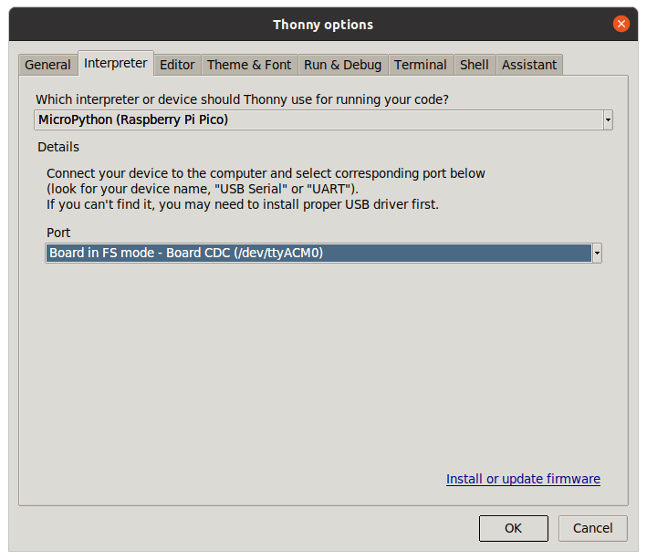
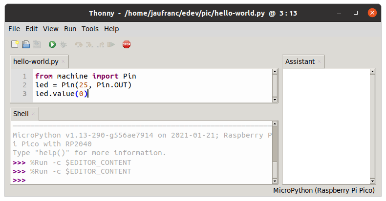
I then went to Run->Select interpreter… to select “MicroPython (Raspberry Pi Pico)“.
From the user interface, I could type some code to turn off the onboard LED:
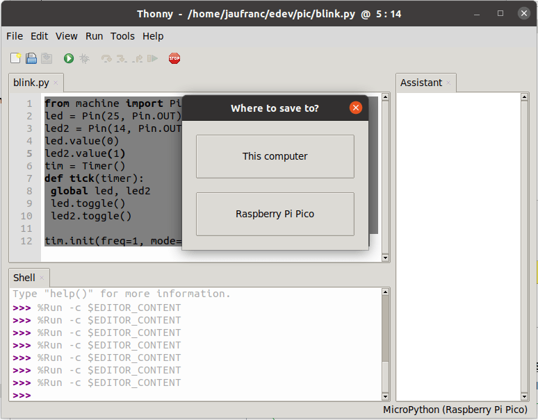
In order to alternatively blink the onboard LED and breadboard LED with a one-second interval, I copied and modified some code from the Python SDK documentation:
|
1 2 3 4 5 6 7 8 9 10 11 12 |
from machine import Pin, Timer led = Pin(25, Pin.OUT) led2 = Pin(14, Pin.OUT) led.value(0) led2.value(1) tim = Timer() def tick(timer): global led, led2 led.toggle() led2.toggle() tim.init(freq=1, mode=Timer.PERIODIC, callback=tick) |
I save the file as blink.py on my PC, and it ran fine. But if you’d like to run the code without a PC, it’s possible to save it to Raspberry Pi Pico. Click on File->Save copy, then on “Raspberry Pi Pico” button,
and save the program as main.py. You can now run the program automatically by connecting your board to any USB power source.
C/C++ on Raspberry Pi Pico
Let’s try the “C/C++ SDK” that is basically all C language, except some tools written in C++. We can go back to the official Getting Started documentation, where we are asked to copy blink.uf2 to Raspberry Pi Pico while in boot mode, and it does blink the onboard LED. It works, and it’s super easy, as the binary is pre-built, but what we really want to do is modify the source code, and build our own binary to blink both the internal and external LED.
So we’ll have to install the C/C++ SDK, dependencies, and samples as follows:
|
1 2 3 4 5 6 |
sudo apt install cmake gcc-arm-none-eabi libnewlib-arm-none-eabi build-essential git clone https://github.com/raspberrypi/pico-sdk cd pico-sdk git submodule update --init cd .. git clone -b master https://github.com/raspberrypi/pico-examples.git |
We can have a look at the blink example in pico-examples/blink/blink.c:
|
1 2 3 4 5 6 7 8 9 10 11 12 13 14 15 16 17 18 19 |
/** * Copyright (c) 2020 Raspberry Pi (Trading) Ltd. * * SPDX-License-Identifier: BSD-3-Clause */ #include "pico/stdlib.h" int main() { const uint LED_PIN = 25; gpio_init(LED_PIN); gpio_set_dir(LED_PIN, GPIO_OUT); while (true) { gpio_put(LED_PIN, 1); sleep_ms(250); gpio_put(LED_PIN, 0); sleep_ms(250); } } |
Good. Before modifying it, we should try to build it by first export the SDK path, and configuring the build:
|
1 2 3 4 5 6 7 8 9 10 11 12 13 14 15 16 17 18 19 20 21 22 23 24 |
$ cd pico-examples/blink $ export PICO_SDK_PATH=../../pico-sdk $ cmake .. Using PICO_SDK_PATH from environment ('../../pico-sdk') Pico SDK is located at /home/jaufranc/edev/sandbox/pico-sdk Defaulting PICO_PLATFORM to rp2040 since not specified. Defaulting PICO platform compiler to pico_arm_gcc since not specified. -- Defaulting build type to 'Release' since not specified. PICO compiler is pico_arm_gcc PICO_GCC_TRIPLE defaulted to arm-none-eabi -- The C compiler identification is GNU 9.2.1 -- The CXX compiler identification is GNU 9.2.1 -- The ASM compiler identification is GNU -- Found assembler: /usr/bin/arm-none-eabi-gcc Defaulting PICO target board to pico since not specified. Using board configuration from /home/jaufranc/edev/sandbox/pico-sdk/src/boards/include/boards/pico.h -- Found Python3: /usr/bin/python3.8 (found version "3.8.5") found components: Interpreter TinyUSB available at /home/jaufranc/edev/sandbox/pico-sdk/lib/tinyusb/src/portable/raspberrypi/rp2040; adding USB support. -- Could NOT find Doxygen (missing: DOXYGEN_EXECUTABLE) ELF2UF2 will need to be built PIOASM will need to be built -- Configuring done -- Generating done -- Build files have been written to: /home/jaufranc/edev/sandbox/pico-examples/blink |
We can now enter the blink directory (a new one, generated by cmake), and run make:
|
1 2 3 4 5 6 7 8 9 10 11 12 13 14 15 16 17 18 19 |
$ cd blink $ make -j8 Scanning dependencies of target ELF2UF2Build Scanning dependencies of target bs2_default [ 0%] Creating directories for 'ELF2UF2Build' [ 0%] No download step for 'ELF2UF2Build' [ 0%] No patch step for 'ELF2UF2Build' [ 0%] No update step for 'ELF2UF2Build' [ 0%] Building ASM object pico_sdk/src/rp2_common/boot_stage2/CMakeFiles/bs2_default.dir/boot2_w25q080.S.obj [ 0%] Performing configure step for 'ELF2UF2Build' [ 0%] Linking ASM executable bs2_default.elf [ 0%] Built target bs2_default ... [ 50%] Building CXX object blink/CMakeFiles/blink.dir/home/jaufranc/edev/sandbox/pico-sdk/src/rp2_common/pico_standard_link/new_delete.cpp.obj [ 50%] Building C object blink/CMakeFiles/blink.dir/home/jaufranc/edev/sandbox/pico-sdk/src/rp2_common/pico_standard_link/binary_info.c.obj [100%] Building C object blink/CMakeFiles/blink.dir/home/jaufranc/edev/sandbox/pico-sdk/src/rp2_common/pico_stdio/stdio.c.obj [100%] Building C object blink/CMakeFiles/blink.dir/home/jaufranc/edev/sandbox/pico-sdk/src/rp2_common/pico_stdio_uart/stdio_uart.c.obj [100%] Linking CXX executable blink.elf [100%] Built target blink |
We now have a bunch of files:
|
1 2 3 4 5 6 7 8 9 10 11 12 |
jaufranc@cnx-laptop-4:~/edev/sandbox/pico-examples/blink/blink$ ls -l total 636 -rwxrwxr-x 1 jaufranc jaufranc 12696 Jan 24 11:42 blink.bin -rw-rw-r-- 1 jaufranc jaufranc 197019 Jan 24 11:42 blink.dis -rwxrwxr-x 1 jaufranc jaufranc 204232 Jan 24 11:42 blink.elf -rw-rw-r-- 1 jaufranc jaufranc 172574 Jan 24 11:42 blink.elf.map -rw-rw-r-- 1 jaufranc jaufranc 35778 Jan 24 11:42 blink.hex -rw-rw-r-- 1 jaufranc jaufranc 25600 Jan 24 11:42 blink.uf2 drwxrwxr-x 4 jaufranc jaufranc 4096 Jan 24 11:41 CMakeFiles -rw-rw-r-- 1 jaufranc jaufranc 1004 Jan 24 11:39 cmake_install.cmake drwxrwxr-x 4 jaufranc jaufranc 4096 Jan 24 11:39 elf2uf2 -rw-rw-r-- 1 jaufranc jaufranc 89141 Jan 24 11:39 Makefile |
The most important ones are blink.uf2 that we can copy to Raspberry Pi Pico to run the program, and blink.elf that can be used by the debugger (OpenOCD + GDB), but that is out of the scope of this getting started guide.
Now that we know how to compile a C program for the Pico board, let’s modify the blink.c example to alternatively turn on and off the onboard LED and external LED connected to pin 14:
|
1 2 3 4 5 6 7 8 9 10 11 12 13 14 15 16 17 18 |
#include "pico/stdlib.h" int main() { const uint LED_PIN = 25; /* onboard LED */ const uint LED2_PIN = 14; /* external LED */ gpio_init(LED_PIN); gpio_set_dir(LED_PIN, GPIO_OUT); gpio_init(LED2_PIN); gpio_set_dir(LED2_PIN, GPIO_OUT); while (true) { gpio_put(LED_PIN, 1); gpio_put(LED2_PIN, 0); sleep_ms(1000); gpio_put(LED_PIN, 0); gpio_put(LED2_PIN, 1); sleep_ms(1000); } } |
and build the program again:
|
1 2 |
cd blink make |
Then enter boot mode and copy blink.uf2 to the board, and success!
We can achieve the same results with either a C or Python program. We’ll have a look at RP2040’s PIO (Programmable IO) interface in an upcoming post, as AFAICT it’s what differentiates Raspberry Pi RP2040 most from other microcontrollers.
I’d like to thank Cytron for sending Raspberry Pi Pico for review. If you are based in ASEAN, you can purchase the board on their store for $4.98, or if you have some time there are offering a $5 carrier board for Raspberry Pi Pico for the same price with the board already soldered that’s expected to ship on February 10th, and available worldwide, not only in ASEAN.

Jean-Luc started CNX Software in 2010 as a part-time endeavor, before quitting his job as a software engineering manager, and starting to write daily news, and reviews full time later in 2011.
Support CNX Software! Donate via cryptocurrencies, become a Patron on Patreon, or purchase goods on Amazon or Aliexpress