$6 WT32-ETH01 is a Tiny ESP32 board with Ethernet

Espressif Systems ESP32 processor supports WiFi, Bluetooth, and Ethernet connectivity. There are only a few boards coming with an Ethernet RJ45 jack out of the box including esp32MX-E ESP32 board, TTGO T-Internet-POE, and Olimex ESP32-Gateway board among others.

Those boards are fine, but they sell for $16 and up, so if you’d like a cheaper and tinier ESP32 board with Ethernet, Wireless Tag WT32-ETH01 may be an option for projects not requiring PoE support.
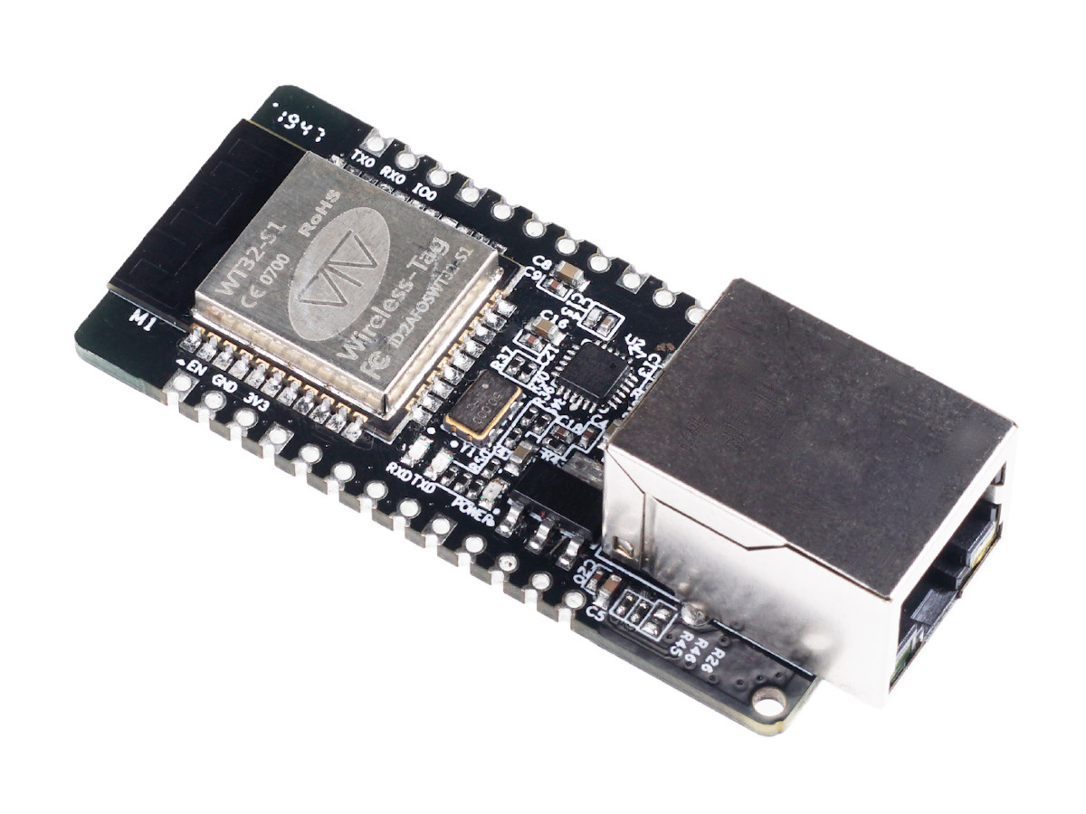
WT32-ETH01 ESP32 Ethernet boardWT32-ETH01 board specifications:

  • Wireless Module – Wireless Tag WT32-S1 based on ESP32 dual-core WiSoC with 4MB flash, on-board antenna
  • Connectivity
    • 10/100M Ethernet via LAN8720A transceiver
    • 2.4 GHz 802.11b/g/n WiFi 4 up to 150 Mbps
    • Bluetooth 4.2 BR/EDR and LE
  • Expansion – 2x 13 through holes and castellated holes with GPIOs, I2C, SPI,  2x UART, EN, LINK, 5V, 3.3V, and GND signals
  • Power Supply – 3.3V or 5.5V via headers, minimum 500 mA; typical operating current: 80 mA
  • Dimensions – 6 x 2.5 cm
  • Temperature Range – -40°C to +85°C
  • Certifications – FCC/CE/RoHS

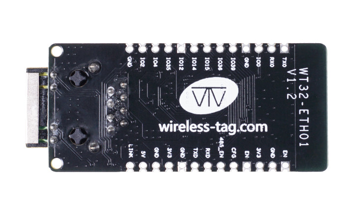
WT32-ETH01 pinoutYou’ll notice there’s no USB on the board, meaning you’ll need one of those cheap USB to TTL boards to program the board, and power it via 5V or 3.3V power input pins.

It looks to be shipping with firmware that’s controlled via AT commands, but as an ESP32 board, you may be able to run other firmware like Arduino or MicroPython with some work. If you’d like to integrate WT32-ETH01 ESP32 Ethernet board into a home automation project, you’ll be glad to know the board has very recently been added to Tasmota firmware.
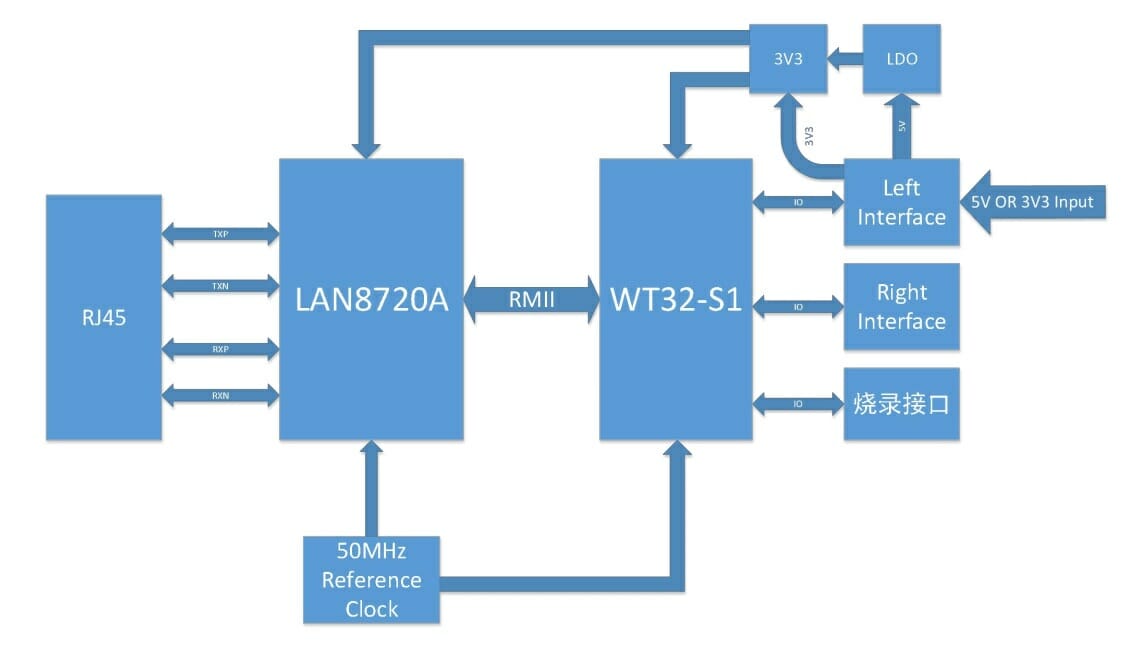
WT32-ETH01 block diagramI first found the board on Seeed Studio where it is up for pre-order for $5.90 with shipping scheduled to start on December 15, but it’s also listed on Aliexpress for about $7, which may end up being cheaper due to shipping options. Note that the green board on Aliexpress is v1.1, while the black board on Seeed Studio is v1.2, and it’s unclear what the differences may be.

Share this:

Support CNX Software! Donate via cryptocurrencies, become a Patron on Patreon, or purchase goods on Amazon or Aliexpress

Radxa Orion O6 Armv9 mini-ITX motherboard
Subscribe
Notify of
guest
The comment form collects your name, email and content to allow us keep track of the comments placed on the website. Please read and accept our website Terms and Privacy Policy to post a comment.
19 Comments
oldest
newest
Rogan Dawes
Rogan Dawes
4 years ago

This is a really nice board for general home automation tasks that you would normally use a plain wireless module for. I can see it being used in e.g. linking alarm systems to the internet (IP serial gateway), bluetooth or WiFi presence detection (mounted on a board with a HLK AC-DC module) reporting via Ethernet, HVAC integration/automation, etc.
A lot of use cases could benefit from Ethernet, while not requiring external power.

cyk
cyk
4 years ago

I don’t know why they didn’t at least add the possibility to use passive PoE. Power injectors for passive PoE are readily available, and cheap. This would’ve made this module the first choice for Ethernet based sensor nodes.

Rogan Dawes
Rogan Dawes
4 years ago

Indeed. Breaking out the 4 unused ethernet pins to a header that could be bridged to the ground and power traces on the PCB (possibly via a switching DCDC converter) would be a simple matter. Or possibly even a bridgeable solder pad. in the case that the passive power would be 5 v or 3v3.

Willy
4 years ago

The problem is the ethernet jack itself. RJ45 connectors with integrated magnetics providing the connectors for the unused pins are rare and more expensive. I wouldn’t be surprised if the limited choice added one dollar to the total BoM, really! At one point one must choose between cost and extensivity :-/

David Willmore
David Willmore
4 years ago

I like the idea of this board, but does anyone else see a problem with trying to mount a castelated board like that when it’s got through hole components sticking out the bottom? You’re going to have a lot of router work on the PCB you mount this to to provide clearance for all of those wires and the ethernet jack mounting studs.

theandamus
theandamus
4 years ago

Nobody’s forcing you to buy it. If it doesn’t meet your needs, just move along.

eas
eas
4 years ago

Did someone force you to leave that comment?

Willy
4 years ago

Indeed! It’s possible they didn’t find an SMD-only ethernet jack. I spent some time searching one for the breadbee, and these connectors (featuring integrated magnetics) are not common at all, and quite expensive.

David Willmore
David Willmore
4 years ago

Oh, I understand how hard it is to find SMD ethernet jacks. There’s plenty of mechanical reasons why such a thing is a bad idea, so there’s not going to be a lot of demand.

What they could have done was to move the jack a little away from the castelated area so that the routing of the host board would be simpler. But how it’s arranged, they made the job a lot harder.

Willy
4 years ago

Yes I definitely agree, the jack could have remained out of the board. Even making a riser board using a rectangular PCB is not easy right now. A few more millimiters would have solved this.

PuceBaboon
4 years ago

David,

The Seeed page has a little more information:-

“…the module is compatible with half-pad and through-hole connectors. The board width is a universal width and therefore, it can be directly soldered to boards, connectors, or even breadboards…”

So it looks as though those aren’t the dreaded, early ESP03 style castellated connectors, thank goodness!

Willy
4 years ago

Indeed it looks possible to use a regular 2.54mm pin array which would then also serve as a riser. But the point still stands that the castellated pads are not practically usable without grinding holes in the board.

David Willmore
David Willmore
4 years ago

Might as well have put normal holes on the board and put 0.1″ headers on it like so many other boards. That’s also a tried-and-true mounting method. 🙂

dgp
dgp
4 years ago

It looks like they should have added 1mm to be board length to get a bit more space between the pins and the connector. Even a few more mm so that the whole connector ends up off the edge of the board on the cheap green 2.54mm proto boards when soldered down.

Jason2866
4 years ago

The only real bad thing imho of this device there are zero useable docs for.

schmurtz
schmurtz
4 years ago

This is very nice ! I presume that the code has to be modified to work on ethernet instead of wifi. Someone has already convert a code with ethernet ? Is it simple ? Possible to use ethernet and wifi in fallback ?

beta-tester
beta-tester
4 years ago

is that WT32-ETH01 module able to flash any firmware you want with the normal tools of ESP-IDF or does the hardware/firmware/efuses/flash not allow to do so?

waz
waz
1 year ago

is the ethernet possible to work on PPPOE to connect to internet and its wifi as an AP?

Boardcon EM3562 Rockchip RK3562 SBC with 8 analog camera inputs