CNXSoft: This is a guest post by Amy working for STONE Technology, a company specializing in industrial liquid crystal display modules
This month, I planned to develop a fingerprint door lock project. When I selected the fingerprint identification module, the project was suspended. However, I thought that since the fingerprint identification module had been purchased, I would simply test it.
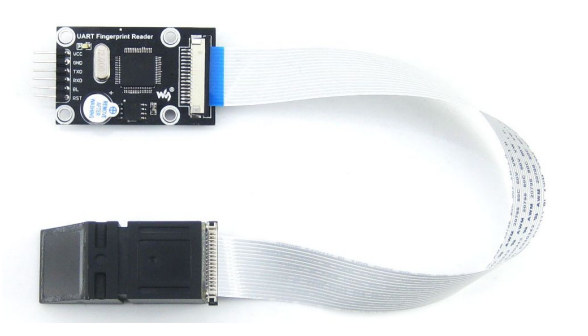
This fingerprint module can be easily purchased online, connected over UART to an MCU board. It supports fingerprint scanning, fingerprint entry, fingerprint comparison, and fingerprint deletion.
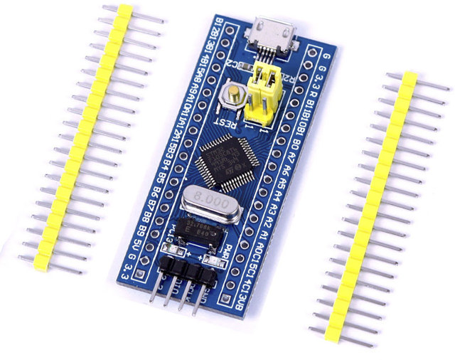
Since the fingerprint module manufacturer provides a demo program for STM32F103 series microcontrollers, I bought a small development board based on STM32F103C8T6.
The demo program of the fingerprint module uses LED lights to prompt the user to enter the fingerprint and compare the status (success or failure). But I want to use an LCD display, so I chose a 480×272 resolution serial LCD display. The specific model of this display is STONE STVC050WT-01, which communicates with MCU through UART, and will be covered in later chapters.
3 hardware components
A total of three hardware modules are used:
- STM32 development board
- Fingerprint module
- STONE STVC050WT-01 LCD display
Fingerprint identification module with UART-TTL
The UART fingerprint reader module is powered by STM32F205 high-speed digital processor from STMicro and integrates a fingerprint algorithm (TFS-9), as well as a high-precision optical sensor (TFS-d400). It supports fingerprint entry, image processing, feature value extraction, template generation, template storage, fingerprint comparison, and search. It exposes a UART interface to be driven from a host microcontroller or processor.
Features
- Sensitive fingerprint sensing and fast identification speed: the fingerprint module adopts high-precision optical path and imaging components, so only hands are needed when using it.
- Stability first: the module adopts STM32F205 MCU with low power consumption and fast speed. Speed & stability are better than Chinese chips.
- “Scientific structure”: the module adopts a modular structure, fingerprint sensor + processing motherboard + algorithm platform.
- Standard 16-pin universal interface: sensors can be independently selected and replaced by optical and other sensors; commercial algorithms are used.
- Easy development: serial port UART operation (directly connect to any single-chip microcomputer with serial port), extremely simple operation. The company provides demo software, learning software, MCU routines, and related tools.
- Openness: free input and output of fingerprint pictures, fingerprint characteristic value files and various fingerprint operations.
Application scenarios
Typical applications include fingerprint locks, fingerprint safes, fingerprint access control, fingerprint attendance, intercoms, personnel identification, permission management, etc…
The fingerprint module can be purchased on Aliexpress for $37.78.
STONE 5-inch STVC050WT-01 4:3 TFT-LCD module
480×272 TFT LCD Display introduction
In this project, I would like to use STONE STVC050WT-01 TFT LCD to display the status of the fingerprint module (entry status, comparison status and deletion of fingerprint data). This display comes with a driver chip, and development software is provided for user interface development. The user simply needs to add the designed UI picture through the software as well as any button or text box as needed, and then generate the configuration file to flash into the display.
The STONE STVC050WT-01 display communicates with MCU through UART-TTL signals.
In theory, the STONE display and fingerprint module can communicate directly. However, due to the different communication data protocols, it is impossible to establish communication. Therefore, an MCU is still needed to handle serial communication.
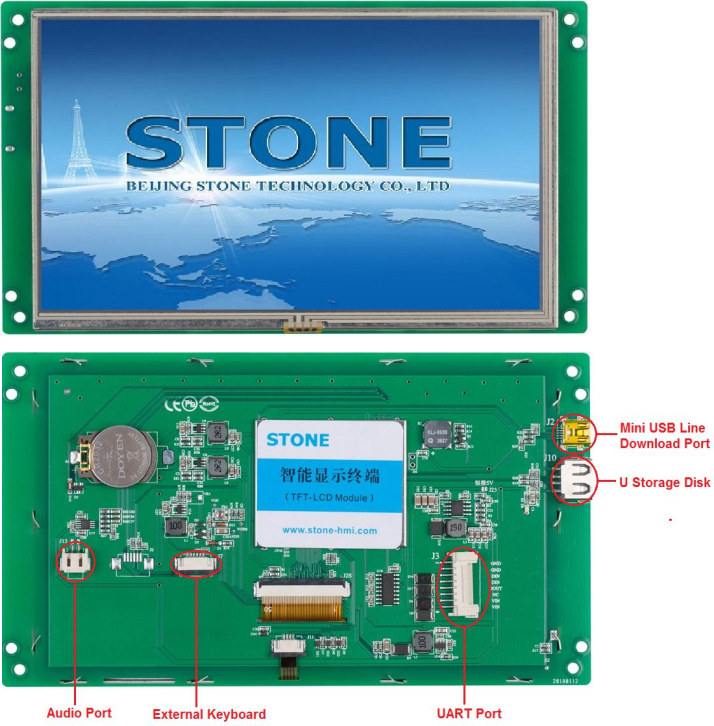 More technical information including the datasheet can be found on the product page, and the module can be purchased on Aliexpress for $37.78.
4 steps to get started with STONE Touch LCD module
- Design the user display interface with PhotoShop, or other photo editing software.
- Design the display logic and button logic with STONE TOOL software, and download the design file onto the display module.
- The MCU communicates with the STONE LCD module through the serial port.
- The data obtained in step 3 shall be used for other actions by MCU.
STONE TOOL Software installation
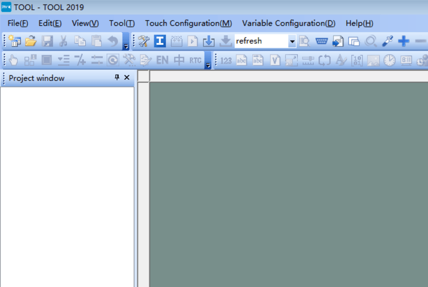
Download the latest version of the STONE TOOL software (currently TOOL 2019) from the official website and install it.
After the software installation is completed, the following interface will be opened:
Click the “File” button in the upper left corner to create a new project, which will be explained in the following sections.
STM32 MCU Board
We used a development board based on STM32F103C8T6 MCU, which can be purchased on Aliexpress for under $2 shipped.
The development environment of STM32
Keil vision is an integrated development environment developed by Keil. Currently, there are several versions of Vision2, Vision3, Vision4, and Vision5. In 2005, Keil was acquired by Arm. In March 2011, the latest integrated development environment Realview MDK development tool released by Arm integrated the latest version of Keil uvision4, and its compiler and debugging tool were optimized for Arm devices.
STM32 uses the KEIL MDK development environment, available on the company’s website.
STONE LCD Fingerprint module test project implementation
Hardware connection to development board and stone LCD module
To make sure that we can write code later, we must first determine the reliability of the hardware connection.
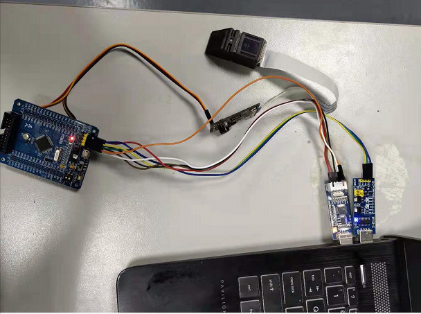
The STM32F103C8T6 development board and STVC050WT-01 TFT-LCD display are connected through UART, and then the STM32F103C8T6 development board and fingerprint module are also connected through UART.
Make sure the hardware connection is correct, then move on to the next step.
Only 1 step to design UI Graphic
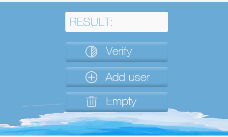
First of all, we need to design a UI display image, which can be designed with PhotoShop software or other image design tools. After designing the UI display image, save the image as JPG format. Here’s the UI I designed in Photoshop.
TFT-LCD Display module design
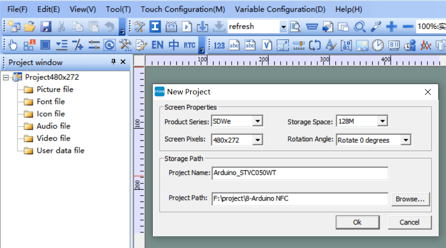
Open the STONE TOOL2019 software and create a new project:
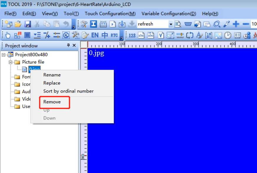
Delete the image that the new project loads by default, and add the UI image that we designed ourselves.
How to add font file via STONE Tool
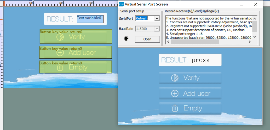
The UI includes a status bar that shows fingerprint verification in real-time, so you need to add a font, as well as text display components and buttons.
The effect is as follows:
How to generate the configuration file for STONE LCD
Once the UI design above is complete, you can generate the configuration file and download it to the STVC050WT-01 display, which is described in the STONE development materials.
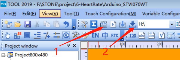
Perform step 1 to generate the configuration file, then insert the USB flash drive into the computer. The flash drive will display. Then click “Download to u-disk” to download the configuration file to the USB flash drive, and then insert the USB flash drive into STVC050WT-01 to complete the upgrade.
How to connect the fingerprint module via UART-TTL
The fingerprint module actually consists of two parts:
- Optical collector
- Driver circuit
The core part is the driver circuit, which is integrated with an STM32F2 series chip. The fingerprint algorithm and scanning algorithm are embedded into the chip, and UART communication is used to get the results making it very convenient for application developers.
Hardware connection:
VCC —— — 3.3v or 5V
GND — — — — — -GND
TXD (fingerprint module serial port send) —— RXD (PC or MCU serial port Rx)
RXD (fingerprint module serial port receive) —— TXD (PC or MCU serial port Tx)
BL (backlight of fingerprint head, not connected) —- IO port
RST(fingerprint module reset, not connected) —— IO port
The first time, you can use a Windows PC to communicate with the fingerprint module through the serial port to do testing. You can find more details on Waveshare Wiki (in Chinese).
STM32 Application development
Visit the official website of the fingerprint module supplier, download the fingerprint module demo program (), and then open the program with KEIL software.
But before going further with software development, let’s connect the hardware first.
Then send instructions through the serial console to check the connection is working properly.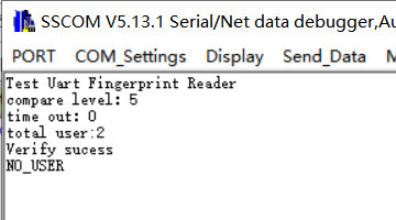 We made some minor modifications to the program with the final code (main.c) as follows:
|
1 2 3 4 5 6 7 8 9 10 11 12 13 14 15 16 17 18 19 20 21 22 23 24 25 26 27 28 29 30 31 32 33 34 35 36 37 38 39 40 41 42 43 44 45 46 47 48 49 50 51 52 53 54 55 56 57 58 59 60 61 62 63 64 65 66 67 68 69 70 71 72 73 74 75 76 77 78 79 80 81 82 83 84 85 86 87 88 89 90 91 92 93 94 95 96 97 98 99 100 101 102 103 104 105 106 107 108 109 110 111 112 113 114 115 116 117 118 119 120 121 122 123 124 125 126 127 128 129 130 131 132 133 134 135 136 137 138 139 140 141 142 143 144 145 146 147 148 149 150 151 152 153 154 155 156 157 158 159 160 161 162 163 164 165 166 167 168 169 170 171 172 173 174 175 176 177 |
#include <stm32f10x.h> #include "usart.h" #include "timer.h" #include "fingerprint.h" #define ADDUSER_BTN_ADDR 0x01 #define VERIFY_BTN_ADDR 0x05 #define CLEAR_BTN_ADDR 0x09 #define TEXT_STATUS_ADDR 0x0c #define USER_SUCESS 0x01 #define USER_FAIL 0X00 u8 data_send[8]= {0xA5, 0x5A, 0x05, 0x82, 0x00, 0x00, 0x00,0x00}; void delay() { u16 i, j; for (i = 0; i < 1000; i++) for(j = 0; j < 10000; j++); } //void USERGPIO_Init(void) //{ // GPIO_InitTypeDef GPIO_InitStructure; // // RCC_APB2PeriphClockCmd(RCC_APB2Periph_GPIOC | RCC_APB2Periph_GPIOF | RCC_APB2Periph_GPIOG, ENABLE); // // GPIO_InitStructure.GPIO_Pin = GPIO_Pin_6|GPIO_Pin_7|GPIO_Pin_8|GPIO_Pin_9; // GPIO_InitStructure.GPIO_Mode = GPIO_Mode_Out_PP; // GPIO_InitStructure.GPIO_Speed = GPIO_Speed_50MHz; // GPIO_Init(GPIOF, &GPIO_InitStructure); // GPIO_ResetBits(GPIOF,GPIO_Pin_6|GPIO_Pin_7|GPIO_Pin_8|GPIO_Pin_9); // GPIO_InitStructure.GPIO_Pin = GPIO_Pin_6|GPIO_Pin_8; // GPIO_InitStructure.GPIO_Mode = GPIO_Mode_IPU; // GPIO_Init(GPIOG, &GPIO_InitStructure); // GPIO_InitStructure.GPIO_Pin = GPIO_Pin_3; // GPIO_Init(GPIOC, &GPIO_InitStructure); //} //u8 key_scan(void) //{ // if(!USER_KEY||!PRESS_KEY||!DEL_KEY) // { // delay(); // if(!USER_KEY) return 1; // if(!PRESS_KEY) return 2; // if(!DEL_KEY) return 3; // } // return 0; //} void UART1_Send_Array(u8 send_array[],unsigned char num) { u8 i=0; while(i<num) { USART_SendData(USART1,send_array[i]); while( USART_GetFlagStatus(USART1,USART_FLAG_TC)!= SET); i++; } } extern u8 USART_RX_BUF[10]; extern u8 USART_RX_END; extern u16 USART_RX_STA; int main(void) { int i = 5; SystemInit(); // USERGPIO_Init(); usart_Configuration(115200,19200); //Ö¸ÎÆÄ£¿éĬÈÏÊÇ19200 // printf("Test Uart Fingerprint Reader\r\n"); SetcompareLevel(5); // printf("compare level£º%d\r\n", GetcompareLevel()); // printf("time out£º%d\r\n",GetTimeOut()); // printf("total user:%d\r\n",GetUserCount()); while(1) { if(USART_RX_END) { //UART1_Send_Array(USART_RX_BUF,8); switch (USART_RX_BUF[5]) { case ADDUSER_BTN_ADDR: //printf("User:%d\r\n",GetUserCount()); switch(AddUser(i)) { case ACK_SUCCESS: i++; //printf("finger add success\r\n"); data_send[5]=TEXT_STATUS_ADDR; data_send[7]=USER_SUCESS; UART1_Send_Array(data_send,8); LED2_ON; delay(); LED2_OFF; break; case ACK_FAIL: //printf("fail\r\n"); data_send[5]=TEXT_STATUS_ADDR; data_send[7]=USER_FAIL; UART1_Send_Array(data_send,8); LED3_ON; delay(); LED3_OFF; break; case ACK_FULL: //printf("full\r\n"); data_send[5]=TEXT_STATUS_ADDR; data_send[7]=USER_FAIL; UART1_Send_Array(data_send,8); LED4_ON; delay(); LED4_OFF; break; } break; case VERIFY_BTN_ADDR: switch(VerifyUser()) { case ACK_SUCCESS: //printf("Verify sucess\r\n"); data_send[5]=TEXT_STATUS_ADDR; data_send[7]=USER_SUCESS; UART1_Send_Array(data_send,8); LED2_ON; delay(); LED2_OFF; break; case ACK_NO_USER: //printf("NO_USER\r\n"); data_send[5]=TEXT_STATUS_ADDR; data_send[7]=USER_FAIL; UART1_Send_Array(data_send,8); LED3_ON; delay(); LED3_OFF; break; case ACK_TIMEOUT: //printf("time out\r\n"); data_send[5]=TEXT_STATUS_ADDR; data_send[7]=USER_FAIL; UART1_Send_Array(data_send,8); LED3_ON; delay(); LED3_OFF; break; case ACK_GO_OUT: //printf("GO OUT\r\n"); data_send[5]=TEXT_STATUS_ADDR; data_send[7]=USER_FAIL; UART1_Send_Array(data_send,8); break; }; break; case CLEAR_BTN_ADDR: ClearAllUser(); //printf("all user remove\r\n"); data_send[5]=TEXT_STATUS_ADDR; data_send[7]=USER_SUCESS; UART1_Send_Array(data_send,8); break; default: USART_RX_END=0; USART_RX_STA=0; } USART_RX_END=0; USART_RX_STA=0; } } } |
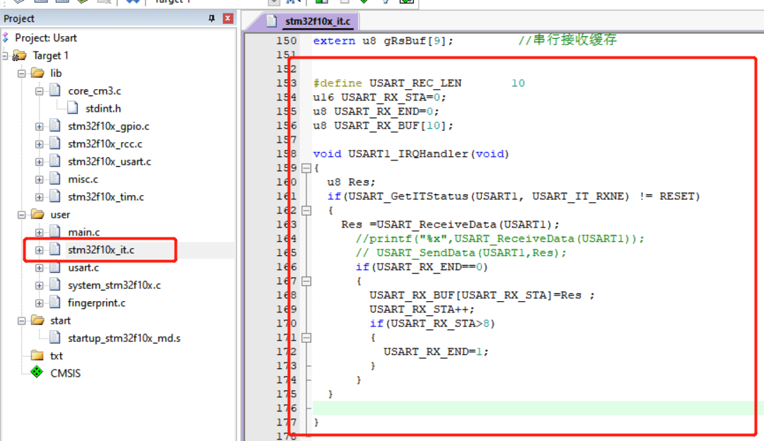
We also had to modify stm32f10x_it.c file to add a USART IRQ handler function.
|
1 2 3 4 5 6 7 8 9 10 11 12 13 14 15 16 17 18 19 20 21 22 23 |
u16 USART_RX_STA=0; u8 USART_RX_END=0; u8 USART_RX_BUF[10]; void USART1_IRQHandler(void) { u8 Res; if(USART_GetITStatus(USART1, USART_IT_RXNE) != RESET) { Res =USART_ReceiveData(USART1); //printf("%x",USART_ReceiveData(USART1)); // USART_SendData(USART1,Res); if(USART_RX_END==0) { USART_RX_BUF[USART_RX_STA]=Res ; USART_RX_STA++; if(USART_RX_STA>8) { USART_RX_END=1; } } } } |
The final result
We only need to connect the STM32 board, fingerprint module, display screen, and power supply. Press the button above the STONE display, and you should be able to add, delete, and verify fingerprints.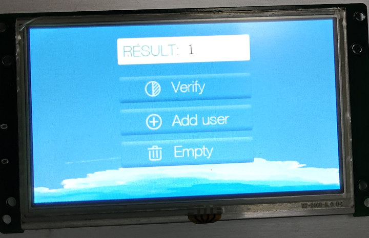

Jean-Luc started CNX Software in 2010 as a part-time endeavor, before quitting his job as a software engineering manager, and starting to write daily news, and reviews full time later in 2011.
Support CNX Software! Donate via cryptocurrencies, become a Patron on Patreon, or purchase goods on Amazon or Aliexpress


