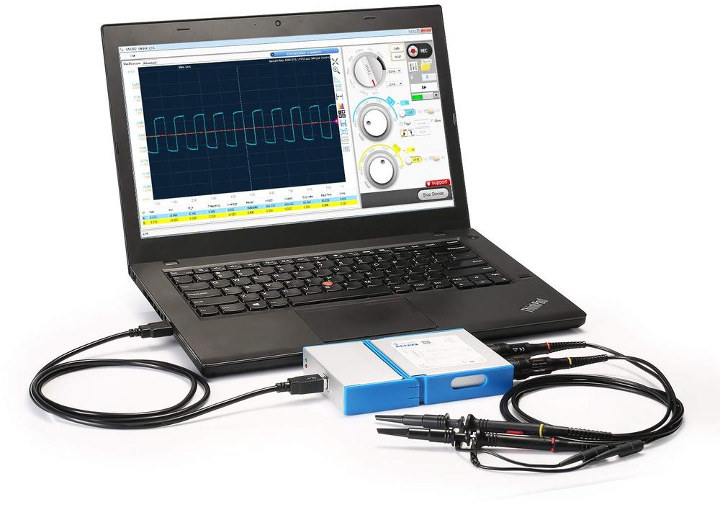
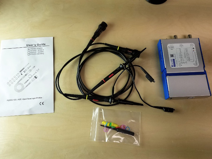
 Hey Karl here. Today we’re going to look at the SainSmart DS802 Dual-channel oscilloscope. I have always wanted to have an oscilloscope and add it to my tools. When SainSmart asked to review the DS802, I was pretty excited. I can get my nerd on and troubleshoot all kinds of things. A couple weeks later it arrives and my anxiety kicks in. How the heck do I review an oscilloscope. I used an oscilloscope in high school in a class called principles of technology. But we never really went into much depth and only looked at the signals generated by a signal generator. I understand the basics. This is written from a perspective of a complete noob.
SainSmart DS802 Specs
Pulled directly from Sainsmarts website:
- Channels: 2 Analog channels
- Interface: USB 2.0
- Output: 1k HZ amplitude 1.5V, 50% duty cycle square wave signal
- Maximum sampling rate: 80 MSps per channel
- Vertical resolution: 8 bit
- Voltage range: ±5v, expandable to ±50v with x10 probe, to ±500v with x100 probe (provided yourself)
- Trigger coupling method: AC, DC
- Timing range: 50ns ~ 2s per line
- Trigger condition: Hardware trigger; Trigger level + rising edge / falling edge trigger
- Trigger mode: Auto, regular, single trigger
- Trigger source: A channel
- Input impedance: 1M / 25pf
- Memory depth: 64k bytes per channel
- Power consumption: < 2 watts
- Supported OS: Windows XP/7/8/10
- Weight: 230g
- Automatic measurement: Maximum, minimum, peak-to-peak, frequency, average, RMS, rise time, positive pulse width, negative pulse width, duty cycle
- Size: 15.25 x 9.32 x 2.31cm
SainSmart DS802 Teardown
In typical CNX Software fashion, I have to tear down the oscilloscope and get a peek inside.
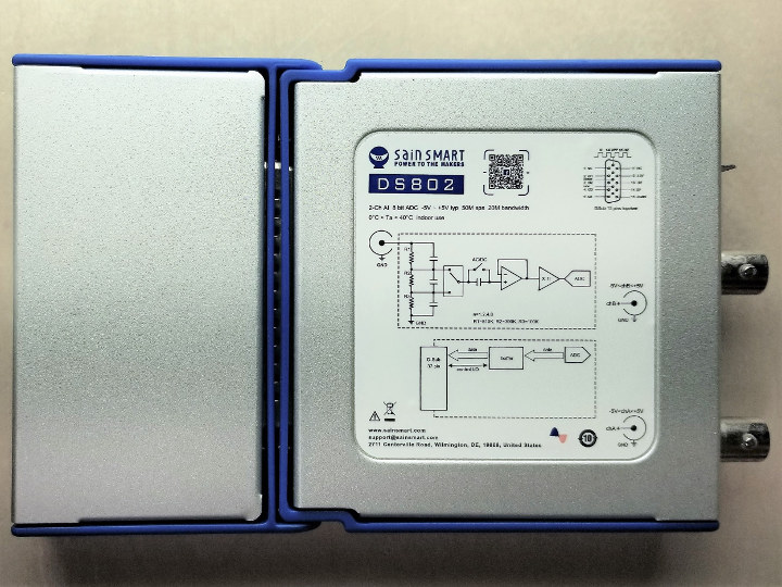
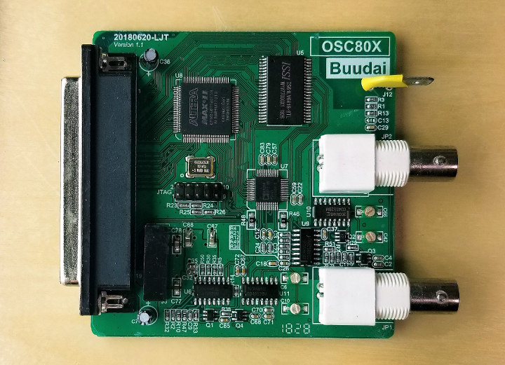
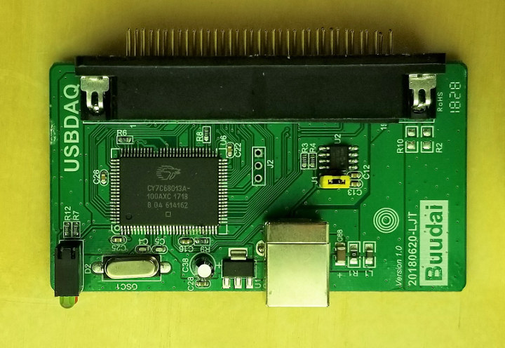
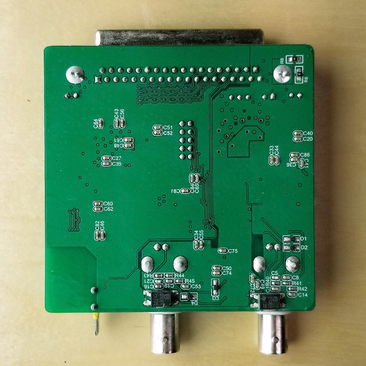
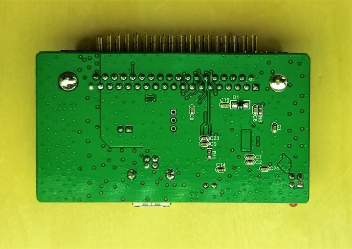
So you can see this is a two-part device. The main oscilloscope park and USB DAQ interface. After a little bit of googling the chips on board (Cypress CY7C68013A + Altera MAX-II CPLD) the DS802 looks like it is a prime candidate for hacking to add features and allow open source software.
SainSmart DS802 Software
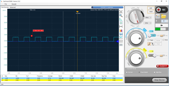
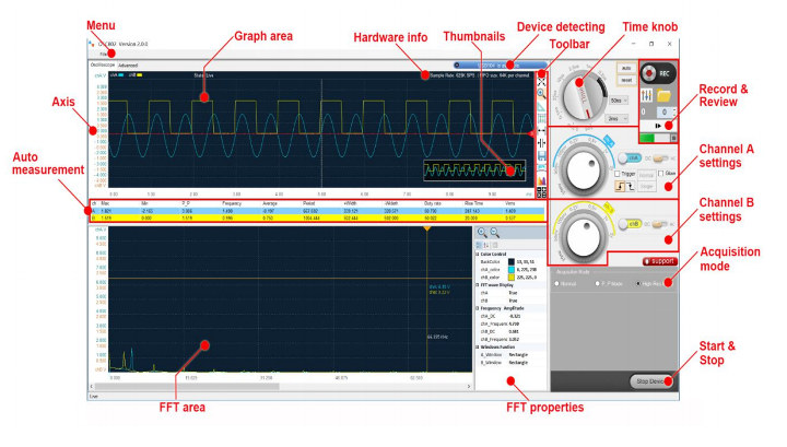
Installing the software was painless and because I was on Windows 10. No additional driver was needed and already built into Windows. I connected the probe to the calibration terminal, clicked start device and I started getting readings on the screen. I took this opportunity to calibrate the probe and made the square wave look as best I could. Across the bottom of the screen are the automatically calculated values calculated values. On the right side of the screen from the top is reset view, zoom in, ruler measurement, cursor measurement, zoom in only on the x-axis, FFT fast Fourier transformation, save as text, save as JPEG, color mod, and finally show hide grid. All of them seemed self explanatory to me and were easy to understand what they did except the FFT button. From www.tek.com
Question:
What is the FFT (Fast Fourier Transform) math function of an oscilloscope useful for?
Answer:
There are a variety of uses that can benefit from viewing the frequency spectrum of a signal. Using the FFT math function on a time domain signal provides the user with frequency domain information and can provide the user a different view of the signal quality, resulting in improved measurement productivity when troubleshooting a device-under-test. Examples include:
- Analyze harmonics in power lines
- Measure harmonic content and distortion in systems
- Characterize noise in DC power supplies
- Test impulse response of filters and systems
- Analyze vibration
Then we have the time knob and voltage knobs for channel A and B. Auto and reset buttons. It has the ability to record in the top right. It can record up to 450 frames. I was not able to stop a recording once it started. Once the measurements were recorded I could open and play, or I could step through the frames. I’m not sure what recording format it is I was assuming it was going to be a text file and record everything. It is some proprietary file. I was only able to play back exactly what I recorded. I was not able to zoom in afterward. And finally the trigger set up.
Testing
I started by reading the included manual and found it is strictly for the probe. I got the software and manual from the SainSmart wiki. It took a minute to figure that the A probe is farthest away from the calibrating terminal. I ended up taking a sharpie and labeling the probes.
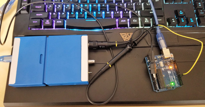 Next thing I did was breakout my Arduino UNO and wrote a little code to test with:
|
1 2 3 4 5 |
void setup() { } void loop() { analogWrite(6, 127); } |
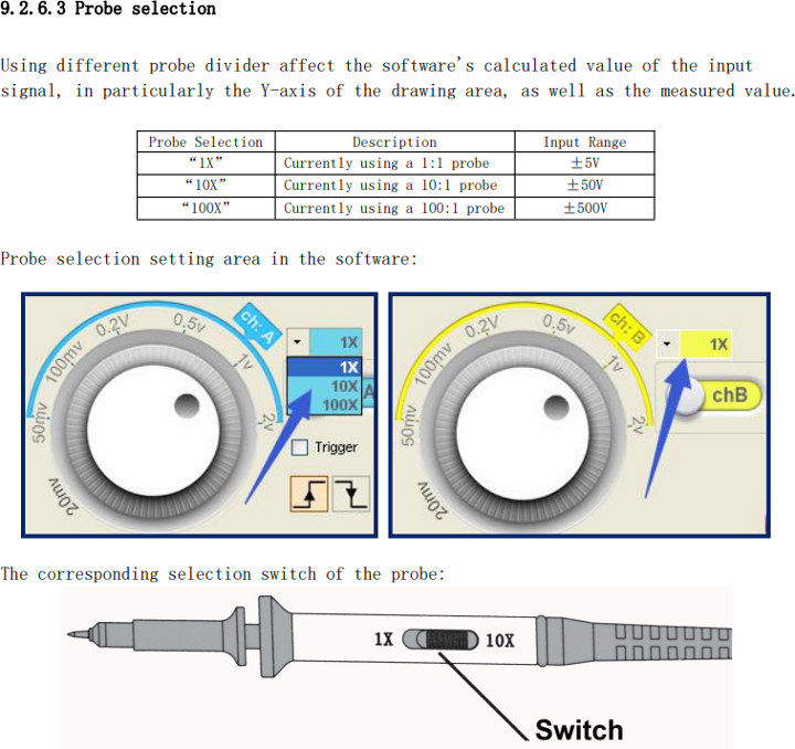
First I set the proper probe setting. I then hit reset and auto and software greeting me with this waveform.
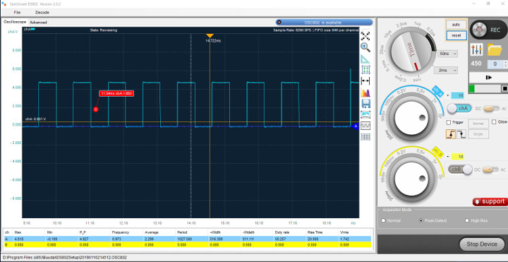
I played around with all the buttons and knobs and drilled down and found this.
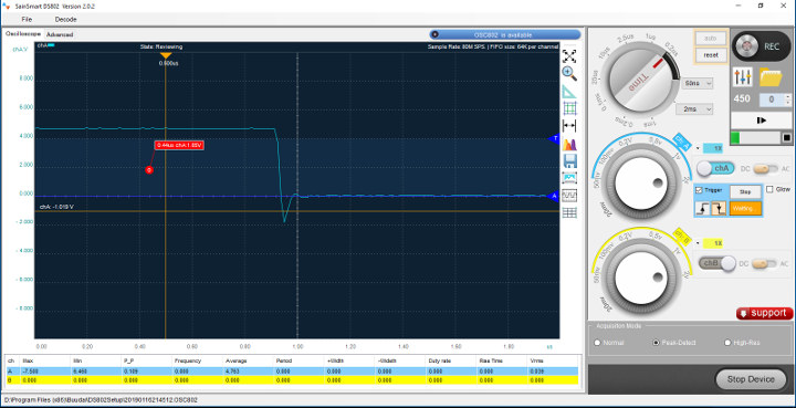
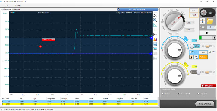
The nice-looking square wave is not as nice as I thought. They have a voltage spike and dip.
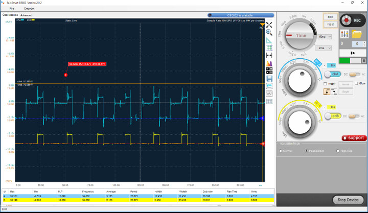
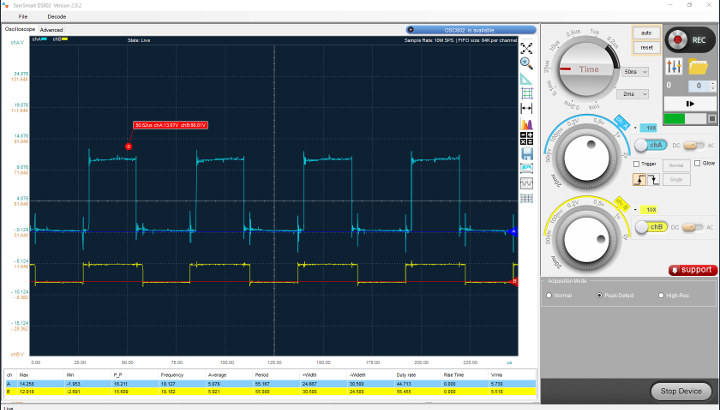
As you guys know I do a lot with 3D printing. Typically they come with inexpensive A4988 stepper drivers. The drivers can be upgraded to Trinamic stepper drivers. They allow for quieter operation and better prints by extending the 16 steps to 256 micro steps. I believe I need a different probe to truly see the microstepping on the oscilloscope. It definitely looks like an improved signal regardless.
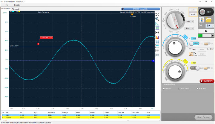
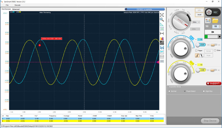
In the software there’s a decode feature for I2C. I wanted to test that out so I pulled out an Arduino and a mega. I found some code and flashed. I was only able to capture the beginning of the transaction.
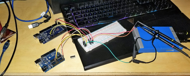
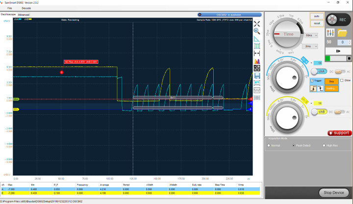
So what do I think? It seems to work as advertised. The only downfall I can see is that it’s a tethered oscilloscope. With some USB extenders it’s not really a big deal for me in my work area. I can load the software on my laptop if I need to be truly mobile. All oscilloscopes may have this but the auto button works well. After making a new connection I press reset and auto and it adjusted the settings and picked up the signal every time with the exception when I was testing the I2C decoding. I had to tell it to use the trigger. There was a hundred milliseconds delay between transmissions. I also had to use the trigger when drilling down and looking at the not so square wave. I do wish it could act like an logic analyzer and get 2 tools with 1 stone.
Please let me know if I missed anything in the comments below…..be gentle. I will do a follow up if warranted.
I would like to thank Sainsmart for sending the DS802. If you would like to pick one up you can get one on the company’s store for $99 currently.

Karl is a technology enthusiast that contributes reviews of TV boxes, 3D printers, and other gadgets for makers.
Support CNX Software! Donate via cryptocurrencies, become a Patron on Patreon, or purchase goods on Amazon or Aliexpress


