I’ve been playing with several ESP32 boards over the months, and tried several firmware images. I started with a tutorial for Arduino Core on ESP32, a few month later I tested ESP32 JavaScript programming with Espruino on ESPino32 board, and recently Espressif Systems sent me ESP32 PICO core development board powered by their ESP32-PICO-D4 SiP, and while I took some pretty photos, I had not used it so far.
So I decided to go with yet another firmware, and this time, I played with MicroPython on ESP32, and will report my experience with basic commands, controlling GPIOs, and WiFi in this getting started post.
Flashing Micropython Firmware to ESP32 Board
Source code is available on Github, as a fork of MicroPython repo as ESP32 support has not been upstreamed yet. We could built the firmware from source, but there’s also a pre-built binary which you can download on MicroPython website.
I’ll be using Ubuntu 16.04 for the instructions, which should be pretty similar for other Linux distributions, especially the ones based on Debian, and if you’re using Windows 10, you should be able to follow the same instructions after installing Windows Subsystem for Linux with Ubuntu on your computer.
Let’s open a terminal, to download the firmware (October 14):
|
1 |
wget http://micropython.org/resources/firmware/esp32-20171014-v1.9.2-277-gd7b373c6.bin |
If you have not done so already, install the latest version of esptool:
|
1 2 3 |
sudo apt install python-pip sudo pip install --upgrade pip sudo pip install esptool --upgrade |
Now connect the board via a micro USB to USB cable to your computer. The log should like like:
|
1 2 3 4 5 6 7 8 9 10 11 12 13 |
[18250.539248] usb 5-3: new full-speed USB device number 2 using ohci-pci [18250.728385] usb 5-3: New USB device found, idVendor=10c4, idProduct=ea60 [18250.728390] usb 5-3: New USB device strings: Mfr=1, Product=2, SerialNumber=3 [18250.728393] usb 5-3: Product: CP2102 USB to UART Bridge Controller [18250.728395] usb 5-3: Manufacturer: Silicon Labs [18250.728398] usb 5-3: SerialNumber: 0001 [18252.249590] usbcore: registered new interface driver usbserial [18252.249620] usbcore: registered new interface driver usbserial_generic [18252.249647] usbserial: USB Serial support registered for generic [18252.252047] usbcore: registered new interface driver cp210x [18252.252067] usbserial: USB Serial support registered for cp210x [18252.252113] cp210x 5-3:1.0: cp210x converter detected [18252.261602] usb 5-3: cp210x converter now attached to ttyUSB0 |
In my case, the device is ttyUSB0, but it may vary depending on the board used. We can now erase the flash, and copy the firmware to the board:
|
1 2 |
esptool.py --port /dev/ttyUSB0 erase_flash esptool.py --chip esp32 --port /dev/ttyUSB0 write_flash -z 0x1000 esp32-20171014-v1.9.2-277-gd7b373c6.bin |
If the last step is successfull, the output should be similar to the one below:
|
1 2 3 4 5 6 7 8 9 10 11 12 13 14 |
esptool.py v2.1 Connecting........_ Chip is unknown ESP32 (revision 0) Uploading stub... Running stub... Stub running... Configuring flash size... Auto-detected Flash size: 4MB Compressed 903392 bytes to 567400... Wrote 903392 bytes (567400 compressed) at 0x00001000 in 50.1 seconds (effective 144.3 kbit/s)... Hash of data verified. Leaving... Hard resetting... |
As a side note, version 2.1 of esptool does not know about ESP32-PICO-D4, but it can still detect an ESP32 device, and the update went through normally.
Hello World Sample / Boot Log with MicroPython
We can test the firmware, by connecting to the board using minicom, screen, putty, or whatever software you feel most comfortable with. I went with minicom, setup a connection to /dev/ttyUSB0 device with 115200 bps baudrate. I immediately tested the print function, and made an hard reset to check out the boot log:
|
1 2 3 4 5 6 7 8 9 10 11 12 13 14 15 |
minicom --baudrate 115200 --device /dev/ttyUSB0 Welcome to minicom 2.7 OPTIONS: I18n Compiled on Feb 7 2016, 13:37:27. Port /dev/ttyUSB0, 14:13:04 Press CTRL-A Z for help on special keys >>> print ("ESP32 PICO Core says Hello!!!") ESP32 PICO Core says Hello!!! >>> import machine >>> machine.reset() |
The reset command will first generate some errors message, before rebooting the board:
|
1 2 3 4 5 6 7 8 9 10 11 12 13 14 15 16 17 18 19 20 21 22 |
rst:0x10 (RTCWDT_RTC_RESET),boot:0x13 (SPI_FAST_FLASH_BOOT) configsip: 188777542, SPIWP:0xee clk_drv:0x00,q_drv:0x00,d_drv:0x00,cs0_drv:0x00,hd_drv:0x00,wp_drv:0x00 mode:DIO, clock div:2 load:0x3fff0010,len:4 load:0x3fff0014,len:4268 load:0x40078000,len:0 load:0x40078000,len:10648 entry 0x4007a56c I (1619) cpu_start: Pro cpu up. I (1619) cpu_start: Single core mode I (1622) heap_init: Initializing. RAM available for dynamic allocation: I (1657) heap_init: At 3FFAE2A0 len 00001D60 (7 KiB): DRAM I (1714) heap_init: At 3FFD4158 len 0000BEA8 (47 KiB): DRAM I (1771) heap_init: At 3FFE0440 len 00003BC0 (14 KiB): D/IRAM I (1831) heap_init: At 3FFE4350 len 0001BCB0 (111 KiB): D/IRAM I (1891) heap_init: At 4008F3A8 len 00010C58 (67 KiB): IRAM I (1949) cpu_start: Pro cpu start user code I (2109) cpu_start: Starting scheduler on PRO CPU. OSError: [Errno 2] ENOENT MicroPython v1.9.2-277-gd7b373c6 on 2017-10-14; ESP32 module with ESP32 Type "help()" for more information. |
We can type help function to get some more help:
|
1 2 3 4 5 6 7 8 9 10 11 12 13 14 15 16 17 18 19 20 21 22 23 24 25 26 27 28 29 30 31 32 33 34 |
>>> help() Welcome to MicroPython on the ESP32! For generic online docs please visit http://docs.micropython.org/ For access to the hardware use the 'machine' module: import machine pin12 = machine.Pin(12, machine.Pin.OUT) pin12.value(1) pin13 = machine.Pin(13, machine.Pin.IN, machine.Pin.PULL_UP) print(pin13.value()) i2c = machine.I2C(scl=machine.Pin(21), sda=machine.Pin(22)) i2c.scan() i2c.writeto(addr, b'1234') i2c.readfrom(addr, 4) Basic WiFi configuration: import network sta_if = network.WLAN(network.STA_IF); sta_if.active(True) sta_if.scan() # Scan for available access points sta_if.connect("<AP_name>", "<password>") # Connect to an AP sta_if.isconnected() # Check for successful connection Control commands: CTRL-A -- on a blank line, enter raw REPL mode CTRL-B -- on a blank line, enter normal REPL mode CTRL-C -- interrupt a running program CTRL-D -- on a blank line, do a soft reset of the board CTRL-E -- on a blank line, enter paste mode For further help on a specific object, type help(obj) For a list of available modules, type help('modules') |
I also often refered to MicroPython 1.9.2 documentation to write this quick start guide.
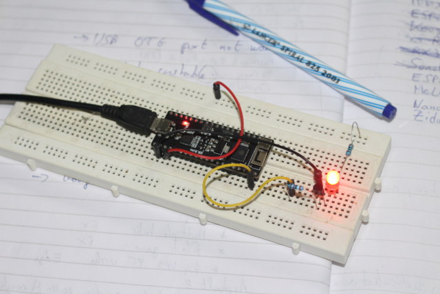
LED Blink Sample with MicroPython
The easiest way to test GPIOs is to connect an LED, since the board does not have any user LED, only the power LED. So I connected an LED to pin 21 via a transistor to ensure enough current passes through it.
Controlling the LED in the command line interface is easy. Import the machine library, set the pin to output, and change the pin level as needed:
|
1 2 3 4 |
>>> import machine >>> pin21 = machine.Pin(21, machine.Pin.OUT) >>> pin21.value(1) >>> pin21.value(0) |
Success! But what about doing a proper blink sample? MicroPython developers’ official PyBoard would show as a USB mass storage drive in you computer, where can copy Python files like boot.py and main.py files, but in the case of ESP32 PICO core, it appears the only option is to use the serial console for programming, as we can’t simply copy files to the board from the host computer.
I found a solution on Techtutorialsx – which also has plenty of articles about MicroPython on ESP32/ESP8266. We need ampy script that can be install from our Linux terminal:
|
1 |
sudo pip install adafruit-ampy --upgrade |
However, the first time I tried it I got an error:
|
1 2 |
import ampy.files as files ImportError: No module named files |
I installed files module, but the error remained. So instead I installed it for Python 3:
|
1 2 3 |
sudo pip install adafruit-ampy --upgrade ampy --version ampy, version 1.0.2 |
I then created blink.py on my computer to blink the LED every 500 ms:
|
1 2 3 4 5 6 7 8 |
import utime import machine pin21 = machine.Pin(21, machine.Pin.OUT) while True: pin21.value(1) utime.sleep_ms(500) pin21.value(0) utime.sleep_ms(500) |
Before uploading the file to the board, you can try to run it as follow:
|
1 |
ampy --port /dev/ttyUSB0 run blink.py |
If you have plenty of errors here, that’s probably because your code is incorrect. Since I’m not very familiar with Python, it happened to me a couple of times, until I got the code right, and the LED was blinking as expected.
Now that we’ve made sure the code works, we can now copy our sample to the board…
|
1 |
ampy --port /dev/ttyUSB0 put blink.py |
… reconnect to the serial console, and verify the file is there:
|
1 2 3 |
>>> import os >>> os.listdir() ['boot.py', 'blink.py'] |
To run the program type the following:
|
1 |
import blink |
The LED should blink again. You can interrupt the program with Ctrl+C, and if you want to soft reset the board, press Ctrl+D.
In order to automatically start the blink program at each boot, rename blink.py to main.py, delete blink.py, and copy main.py instead:
|
1 2 3 |
mv blink.py main.py ampy --port /dev/ttyUSB0 rm blink.py ampy --port /dev/ttyUSB0 put main.py |
Power cycle the board, and the LED should start blinking almost immediately.
ESP32 WiFi with MicroPython (Station and AP modes)
We’ve got GPIOs working, but one of the most important feature of ESP32 is obvisouly WiFi. I’ll start by configuring the board in station mode. First import the network library, set the board to station mode, and scan access points:
|
1 2 3 |
import network sta_if = network.WLAN(network.STA_IF); sta_if.active(True) sta_if.scan() |
The latter should return a list of access points with ssid, bssid, channel, RSSI, authmode, and hidden status as explained here.
|
1 2 |
I (1171360) wifi: event 1 [(b'CNX-SOFTWARE', b'\xd0\xc7\xc0\xf9\xeb\x0f', 6, -51, 4, False), (b'CNX-TRANSLATION', b'\x94\x0cm\xe6[\x10', 1, -52, 4, False), (b'sonoff-office', b'^\xcf\x7f \xda\xa1', 1, -52, 3, False)] |
I can then connect the board to one of the access points with:
|
1 2 3 4 5 6 7 8 9 10 |
>>> sta_if.connect("CNX-TRANSLATION", "password") >>> I (1466750) wifi: n:1 1, o:1 0, ap:255 255, sta:1 1, prof:1 I (1467310) wifi: state: init -> auth (b0) I (1467310) wifi: state: auth -> assoc (0) I (1467320) wifi: state: assoc -> run (10) I (1467330) wifi: connected with CNX-TRANSLATION, channel 1 I (1467330) wifi: event 4 I (1469190) event: ip: 192.168.0.105, mask: 255.255.255.0, gw: 192.168.0.1 I (1469190) wifi: GOT_IP I (1470320) wifi: pm start, type:0 |
The log above with IP address should give a clue, but you can check connection status with the following function:
|
1 2 |
>>> sta_if.isconnected() True |
and use ifconfig to get the IP info:
|
1 2 |
>>> sta_if.ifconfig() ('192.168.0.105', '255.255.255.0', '192.168.0.1', '192.168.0.1') |
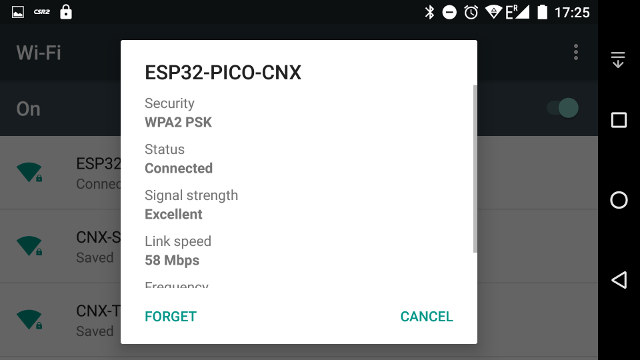
Switching to AP mode is easy with the three commands below configuring the board with ESP32-PICO-CNX SSID:
|
1 2 3 4 5 6 7 8 9 10 |
>>> ap = network.WLAN(network.AP_IF) >>> ap.active(True) I (1801120) wifi: mode : sta (d8:a0:1d:00:05:c4) + softAP (d8:a0:1d:00:05:c5) I (1801120) wifi: pm stop, total sleep time: 0/330800928 I (1801120) wifi: event 13 True >>> ap.config(essid='ESP32-PICO-CNX') I (1823060) wifi: event 14 I (1823060) wifi: event 13 |
At this stage I can see ESP32-PICO-CNX on my phone, but it’s an open connection. We can change that with authmode option that can take 5 values:
- 0 – open
- 1 – WEP
- 2 – WPA-PSK
- 3 – WPA2-PSK
- 4 – WPA/WPA2-PSK
I’ll use WPA2-PSK and define the password with the config function.
|
1 |
ap.config(authmode=3, password='password') |
Working as planned…
ESP32 Web Server with Micropython
Many ESP32 project will require a web interface for monitoring or configuration. Let’s first setup the board as an access point using the command we’ve used above:
|
1 2 3 4 5 |
import network ap = network.WLAN(network.AP_IF) ap.active(True) ap.config(essid='ESP32-PICO-CNX') ap.config(authmode=3, password='password') |
Now create webserver.py file based on Python code found here that’s supposed to return the status of some GPIO pins in an HTML table:
|
1 2 3 4 5 6 7 8 9 10 11 12 13 14 15 16 17 18 19 20 21 22 23 24 25 26 27 28 29 30 31 32 33 |
import machine pins = [machine.Pin(i, machine.Pin.IN) for i in (0, 2, 4, 5, 12, 13, 14, 15)] html = """<!DOCTYPE html> <html> <head> <title>ESP32 Pins</title> </head> <body> <h1>ESP32 Pins</h1> <table border="1"> <tr><th>Pin</th><th>Value</th></tr> %s </table> </body> </html> """ import socket addr = socket.getaddrinfo('0.0.0.0', 80)[0][-1] s = socket.socket() s.bind(addr) s.listen(1) print('listening on', addr) while True: cl, addr = s.accept() print('client connected from', addr) cl_file = cl.makefile('rwb', 0) while True: line = cl_file.readline() if not line or line == b'\r\n': break rows = ['<tr><td>%s</td><td>%d</td></tr>' % (str(p), p.value()) for p in pins] response = html % '\n'.join(rows) cl.send(response) cl.close() |
Copy the file to the board:
|
1 |
ampy --port /dev/ttyUSB0 run webserver.py |
Start the serial console again, import/run the python sample we’ve copied, and connect to the board (in my case http://192.168.4.1):
|
1 2 3 4 |
>>> import webserver I (90557) modsocket: Initializing listening on ('0.0.0.0', 80) client connected from ('192.168.4.2', 60042) |
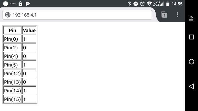
It works as expected, but we wrote the HTML code inside the Python file, and you need to handle socket programming by yourself. To further simply the task, some MicroPython web servers such as MicroWebSrv, and Picoweb are available.
MicroWebSrv (Not working yet for me)
I tried to install MicroWebSrv first, but never managed to make it work. I still reproduce the step I followed in case somebody finds out what I did wrong. I got the code, and copied files from the Linux terminal:
|
1 2 3 4 5 6 7 |
git clone https://github.com/jczic/MicroWebSrv cd MicroWebSrv ampy --port /dev/ttyUSB0 put microWebSocket.py ampy --port /dev/ttyUSB0 put microWebTemplate.py ampy --port /dev/ttyUSB0 put microWebSrv.py ampy --port /dev/ttyUSB0 mkdir flash ampy --port /dev/ttyUSB0 put www /flash/www |
We can check the files are where they are supposed to be:
|
1 2 3 4 5 6 7 8 9 10 11 12 13 14 |
ampy --port /dev/ttyUSB0 ls boot.py microWebSocket.py microWebTemplate.py microWebSrv.py flash ampy --port /dev/ttyUSB0 ls flash/www wstest.html style.css test.pyhtml pdf.png favicon.ico test.pdf |
Go into the terminal (aka REPL console) to start a basic example, after setting up a connection:
|
1 2 3 |
from microWebSrv import MicroWebSrv mws = MicroWebSrv() # TCP port 80 and files in /flash/www mws.Start() # Starts server in a new thread |
I could connect to the server, but I would always get 404 error.
PicoWeb
So instead I switched to picoweb, adapting the instructions here and there. It’s very easy to install. First make sure you have a working Internet connection in your board (i.e. set station mode), and install the web server with upip:
|
1 2 |
import picoweb upip.install('picoweb') |
That’s the output if everything goes according to plans:
|
1 2 3 4 5 6 7 8 |
Installing to: /lib/ Warning: pypi.python.org SSL certificate is not validated Installing picoweb 1.2.2 from https://pypi.python.org/packages/22/be/7e7cabe1acz Installing micropython-uasyncio 1.2.2 from https://pypi.python.org/packages/40/z Installing micropython-pkg_resources 0.2.1 from https://pypi.python.org/packagez Installing micropython-uasyncio.core 1.5 from https://pypi.python.org/packages/z Installing micropython-logging 0.1.3 from https://pypi.python.org/packages/31/6z >>> |
Now let’s go back to the host computer to create an html document, for example index.html:
|
1 2 3 4 5 6 7 8 9 10 11 |
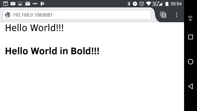
<!DOCTYPE HTML> <html lang="en"> <head> <meta charset="utf-8"> <title>Picoweb on ESP32 PICO Core</title> </head> <body> <p>Hello World!!!</p> <p><b>Hello World in Bold!!!</b></p> </body> </html> |
as well as picowebtest.py sample file that will request the HTML page from the board, and return it to the client.
|
1 2 3 4 5 6 7 8 9 10 11 12 13 14 |
import picoweb app = picoweb.WebApp(__name__) @app.route("/") def index(req, resp): yield from picoweb.start_response(resp, content_type = "text/html") htmlFile = open('index.html', 'r') for line in htmlFile: yield from resp.awrite(line) app.run(debug=True, host = "192.168.0.108") |
You’ll need to change “192.168.0.108” by the IP address of your board.
Let’s copy both files to the board…
|
1 2 |
ampy --port /dev/ttyUSB0 put index.html ampy --port /dev/ttyUSB0 put picowebtest.py |
… go back to the serial console, connect in station mode, and run the sample:
|
1 2 3 4 5 6 |
import network sta_if = network.WLAN(network.STA_IF); sta_if.active(True) sta_if.connect("CNX-TRANSLATION", "password") import picowebtest I (100468) modsocket: Initializing * Running on http://192.168.0.108:8081/ |
Type or copy/paste the URL in the last line into a web browser, and you should get the output below.
 ESP32 Bluetooth with MicroPython
There’s no Bluetooth support in the official MicroPython documentation, because it’s work in progress, and for the most adventurous MrSulry released an alpha version a few days ago. The Bluetooth API is also in flux, but the basic code to enable Bluetooth should look like:
|
1 2 |
import network bluetooth = network.Bluetooth() |
I’ll update that section once Bluetooth makes it to the stable release, and/or when I’m sure the API is frozen.
Other ESP32 (Micro)Python Resources
I’ve just covered a few things that can be done with MicroPyhon on ESP32, and beside the official documentation, you can also check the various MicroPython ESP32 tutoral on techtutorialsx blog. Loboris also made another MicroPython ESP32 firmware that supports pSRAM as MicroPython may use a lot of RAM. If you’re interested in Python for ESP32, but Zerynth is another option for Python on ESP32 that works with an IDE/GUI available for Windows, Linux and MAC OS X. [Update: Yet other options are Pumbaa a port of MicroPython running on top of Simba, and Pycom version of MicroPython]

Jean-Luc started CNX Software in 2010 as a part-time endeavor, before quitting his job as a software engineering manager, and starting to write daily news, and reviews full time later in 2011.
Support CNX Software! Donate via cryptocurrencies, become a Patron on Patreon, or purchase goods on Amazon or Aliexpress