NanoPi NEO 2 is a tiny 64-bit ARM development board powered by Allwinner H5 processor. FriendlyELEC sent me a couple of NEO 2 samples together with their BakeBit Start Kit with a NanoHat and various modules via GPIOs, analog input or I2C. I’ve already tested both Armbian with Linux 4.11 and Ubuntu Core Qt with Linux 3.10, and ran a few benchmarks on NanoPi NEO 2. You would normally prefer to use the Armbian image with Linux mainline since it provided better performance, but at the time I was told GPIO support was not there.
Configuring NanoPi NEO 2 board with BakeBit library
So this week-end, when I decided to test GPIO support and BakeBit Starter Kit, I decided to follow this advice, especially nanopi-neo2-ubuntu-core-qte-sd4g-20170329.img.zip image is still the recommended one in the Wiki. So I went with that image.
I’ll use Python examples from Bakebit library, but if you prefer something similar to WiringPi, you may consider using WiringNP library directly instead of using Bakebit. Since NanoHat Hub comes with header with digital I/O (including 2 PWM), analog input, I2C and UART interfaces, I’ll make sure I try samples for all interfaces I have hardware for. FriendlyELEC did not include a module with a UART interface, so I’ll skip that one.
I followed instructions in BakeBit wiki from a terminal which you can access from the serial console or SSH. First, we need to retrieve the source code:
|
1 2 |
cd ~ git clone https://github.com/friendlyarm/BakeBit.git |
Then we can start the installation:
|
1 2 3 |
cd BakeBit/Script chmod +x install.sh sudo ./install.sh |
The last line will install the following dependencies:
- python2.7 python2.7
- python-pip alternative Python package installer
- git fast, scalable, distributed revision control system
- libi2c-dev userspace I2C programming library development files
- python-serial pyserial – module encapsulating access for the serial port
- i2c-tools This Python module allows SMBus access through the I2C /dv
- python-smbus Python bindings for Linux SMBus access through i2c-dev
- minicom friendly menu driven serial communication program
- psutil a cross-platform process and system utilities module for n
- WiringNP a GPIO access library for NanoPi NEO
This will take a while, and after it’s done, the board will automatically reboot.
We can check if everything is properly running, but try out one of the Python scripts:
|
1 2 3 4 5 6 7 8 |
cd ~/BakeBit/Software/Python sudo python bakebit_sound_sensor.py Traceback (most recent call last): File "bakebit_sound_sensor.py", line 37, in <module> import bakebit File "/home/pi/BakeBit/Software/Python/bakebit.py", line 61, in <module> bus = smbus.SMBus(0) IOError: [Errno 2] No such file or directory |
hmm, python-smbus was supposed to be installed via the installation script. Let’s try to install it manually:
|
1 2 3 4 |
sudo pip install python-smbus Collecting python-smbus Could not find a version that satisfies the requirement python-smbus (from ve) No matching distribution found for python-smbus |
Running the command again with verbose option shows the download URL is not valid:
|
1 2 3 4 5 6 7 8 9 10 11 |
sudo pip install -vvv python-smbus Collecting python-smbus 1 location(s) to search for versions of python-smbus: * https://pypi.python.org/simple/python-smbus/ Getting page https://pypi.python.org/simple/python-smbus/ Looking up "https://pypi.python.org/simple/python-smbus/" in the cache No cache entry available Starting new HTTPS connection (1): pypi.python.org "GET /simple/python-smbus/ HTTP/1.1" 404 28063 Status code 404 not in [200, 203, 300, 301] Could not fetch URL https://pypi.python.org/simple/python-smbus/ |
So I went to https://pypi.python.org/simple/ looking for another python-smbus library in case the name has changed, and I finally installed the pysmbus:
|
1 |
sudo pip install pysmbus |
I could go further, but the I2C bus was not detected:
|
1 2 3 4 5 6 7 8 9 10 |
sudo python bakebit_sound_sensor.py [sudo] password for pi: Traceback (most recent call last): File "bakebit_sound_sensor.py", line 37, in <module> import bakebit File "/home/pi/BakeBit/Software/Python/bakebit.py", line 61, in <module> bus = smbus.SMBus(0) File "/usr/local/lib/python2.7/dist-packages/smbus.py", line 51, in __init__ self.fd = posix.open("/dev/i2c-{}".format(bus), posix.O_RDWR) OSError: [Errno 2] No such file or directory: '/dev/i2c-0' |
So maybe the driver needs to be loaded. But running sudo modprobe i2c_sunxi it does nothing, and I could notice the .ko file is missing from the image…
So let’s try to build the source code for the board following the Wiki intructions:
|
1 |
git clone https://github.com/friendlyarm/h5_lichee.git lichee |
We also need to install required build packages…
|
1 2 3 4 5 |
sudo apt-get install gawk git gnupg flex bison gperf build-essential \ zip curl libc6-dev libncurses5-dev:i386 x11proto-core-dev \ libx11-dev:i386 libreadline6-dev:i386 libgl1-mesa-glx:i386 \ libgl1-mesa-dev g++-multilib tofrodos \ python-markdown libxml2-utils xsltproc zlib1g-dev:i386 |
… download gcc-linaro-aarch64.tar.xz toolchain, and copy it to lichee/brandy/toolchain directory (do not extract it, it will be done by the build script).
Now we can try to build the kernel for NanoPi NEO 2 (and other Allwinner H5 boards).
|
1 2 |
cd lichee/fa_tools/ ./build.sh -b nanopi-neo2 -p linux -t kernel |
and it failed with more errors possible related to CROSS_COMPILE flag. There must be a better solution… FriendlyELEC guys might not work on Saturday afternoon, and while I did contact them, I decided to try one of their more recent images with Linux 4.11 available here.
Let’s pick nanopi-neo2_ubuntu-core-xenial_4.11.0_20170518.img.zip since it has a similar name, and is much newer (released 3 days ago). I repeated the installation procedure above, and …
|
1 2 3 4 |
sudo python bakebit_sound_sensor.py sensor_value = 0 sensor_value = 57 sensor_value = 59 |
Success! Albeit after 4 to 5 hours of work… Let’s connect hardware to ind out whether it actually works, and not just runs.
Analog Input and Digital Output – Sound Sensor Demo
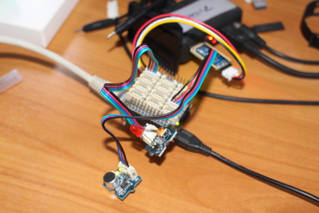
The simplest demo would be to use the LED module, but let’s do something more fun with the Sound Sensor demo I found in BakerBit Starter Kit printed user’s manual, and which will allow us to use both digital output with the LED module connected to D5 header, and analog input with the Sound sensor module connected to A0 header. Just remember the long LED pin is the positive one.
You can run the code as follows:
|
1 2 |
cd ~/BakeBit/Software/Python sudo python bakebit_sound_sensor.py |
I changed the source a bit including the detection threshold, and timing to make it more responsive:
|
1 2 3 4 5 6 7 8 9 10 11 12 13 14 15 16 17 18 19 20 21 22 23 24 25 26 27 28 29 30 31 32 33 34 |
import time import bakebit # Connect the BakeBit Sound Sensor to analog port A0 # SIG,NC,VCC,GND sound_sensor = 0 # Connect the BakeBit LED to digital port D5 # SIG,NC,VCC,GND led = 5 bakebit.pinMode(sound_sensor,"INPUT") bakebit.pinMode(led,"OUTPUT") # The threshold to turn the led on 300.00 * 5 / 1024 = 1.46v threshold_value = 300 while True: try: # Read the sound level sensor_value = bakebit.analogRead(sound_sensor) # If loud, illuminate LED, otherwise dim if sensor_value > threshold_value: bakebit.digitalWrite(led,1) sleep 1 else: bakebit.digitalWrite(led,0) print("sensor_value = %d" %sensor_value) time.sleep(.01) except IOError: print ("Error") |
The LED will turn on each time the the sound level (actually analog voltage) is above 1.46V.
PWM and Analog Input – Servo and Rotary Angle Sensor Demo
We can test PWM output using the Servo module connected to D5 header, and control it using the rotary angle sensor module connected the A0 analog input header .
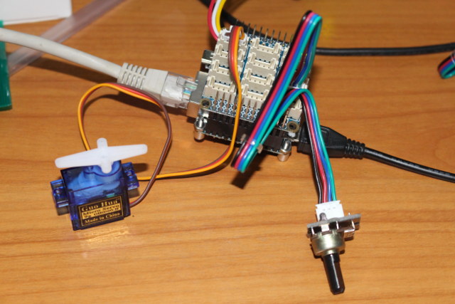
The sample for the demo runs fine, and use the potentiometer is detected:
|
1 2 3 4 5 6 7 8 9 |
sudo python bakebit_prj_Servo_And_RotaryAngleSensor.py sensor_value = 73 voltage = 0.36 degrees = 12 sensor_value = 107 voltage = 0.52 degrees = 18 sensor_value = 282 voltage = 1.38 degrees = 49 sensor_value = 491 voltage = 2.40 degrees = 86 sensor_value = 656 voltage = 3.21 degrees = 115 sensor_value = 672 voltage = 3.28 degrees = 118 sensor_value = 622 voltage = 3.04 degrees = 109 sensor_value = 371 voltage = 1.81 degrees = 65 |
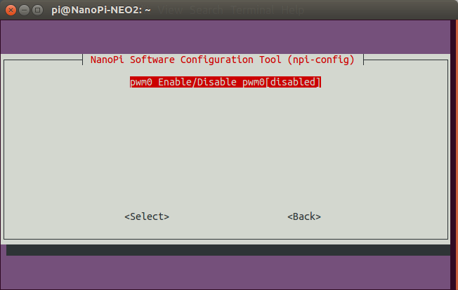
However, the servo is not moving at all. Raspberry Pi relies on rpi-config to enable things like I2C and other I/Os, and I noticed npi-config in the Wiki for NEO 2. So I ran it, and sure enough PWM was disabled.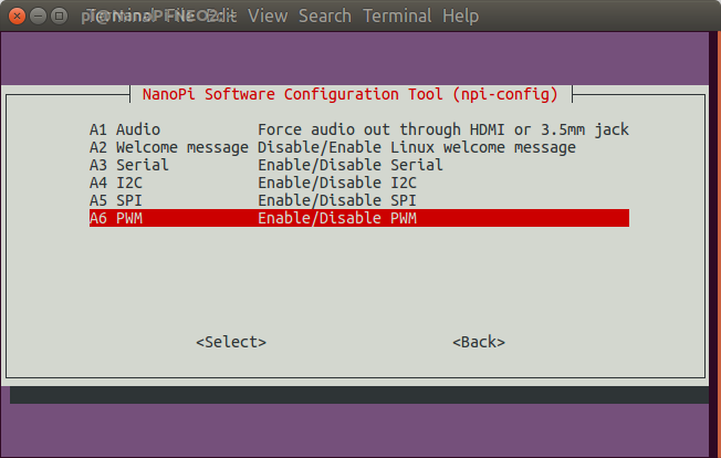
So I enabled it, and answered Yes when I was asked to reboot. The only problem is that it would not boot anymore, with the system blocked at:
|
1 2 3 4 5 6 7 8 |
reading sun50i-h5-nanopi-neo2.dtb 19229 bytes read in 30 ms (625 KiB/s) ## Flattened Device Tree blob at 48000000 Booting using the fdt blob at 0x48000000 Loading Ramdisk to 49b00000, end 4a000000 ... OK Loading Device Tree to 0000000049af8000, end 0000000049affb1c ... OK Starting kernel ... |
So maybe something went wrong during the process, so I re-flashed the Ubuntu image, reinstalled BakeBit, and re-enabled PWM0. But before rebooting, I checked the boot directory, and noticed boot.cmd, boot.scr, and the device tree file (sun50i-h5-nanopi-neo2.dtb) had been modified. The DTB looks fine, as I could decode it, and find the pwm section:
|
1 2 3 4 5 6 7 |
dtc -I dtb -O dts sun50i-h5-nanopi-neo2.dtb | grep -i pwm pwm0 { function = "pwm0"; pwm@01c21400 { compatible = "allwinner,sun8i-h3-pwm"; #pwm-cells = <0x3>; pwm0 = "/soc/pwm@01c21400"; |
Let’s reboot the board. Exact same problem with the boot stuck at “Starting kernel…”. So there’s something wrong with the way npi-config modifies one or more of the files. With hindsight, I should have made a backup of those three files before enabling PWM the second time… I’ll give up on PWM for now, and ask FriendlyELEC to look into it.
I2C and Analog Input – OLED UI controlled with Joystick
The final test I’ll use the I2C OLED display module connected to one of the I2C headers, together with the analog joystick module connected to A0 header.
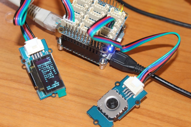
Let’s run the sample for the demo:
|
1 2 3 4 5 6 7 8 9 |
python bakebit_prj_UIControl_via_Joystick.py ('x =', 538, ' y =', 541, ' opIndex=', 0) ('x =', 538, ' y =', 541, ' opIndex=', 0) ('x =', 521, ' y =', 1023, ' opIndex=', 1) left ('x =', 0, ' y =', 769, ' opIndex=', 1) left ('x =', 518, ' y =', 199, ' opIndex=', 0) ('x =', 518, ' y =', 1023, ' opIndex=', 1) |
It works, but there’s a bit of a lag, and the sample may have to be improved to better detect various states. I’ll show what I mean in the video below.
The bad parts are that documentation is not up-to-date, enabling PWM will crash the image, and while the Python sample do demonstrate IO capabilities, they should probably be improved to be more responsive. The good part is that we’re getting there, the hardware kit is a really nice, and I think the documentation and software should become much better in June, as FriendlyELEC has shown to be responsive to the community issues.
What? Python sucks? You can use C language with GPIOs too
If Python is not your favorite language, FriendlyELEC also provided some C languages samples in the C directory:
|
1 2 3 4 |
pi@NanoPi-NEO2:~/BakeBit/Software/C$ ls bakebit_analog_read.c bakebit_digital_read.c README.md bakebit_analog_write.c bakebit_digital_write.c bakebit.c bakebit.h |
As we’ve seen above, Bakebit library appears to rely on WiringNP, and you’d normally be able to list the GPIOs as follows:
|
1 2 3 4 5 |
sudo gpio readall piBoardRev: Unable to determine board revision from /proc/cpuinfo -> Is not H3 based board -> You may want to check: -> http://www.lemaker.org/ |
The utility is not too happy about seeing an Allwinner H5 board. But maybe the library in the board is not up-to-date, so I have built it from source:
|
1 2 3 4 |
git clone https://github.com/friendlyarm/WiringNP cd WiringNP/ chmod 755 build ./build |
and run the gpio sample again:
|
1 2 3 4 5 6 7 8 9 10 11 12 13 14 15 16 17 18 19 20 21 22 23 24 25 26 |
sudo ./gpio/gpio readall +-----+-----+----------+------+---+-NanoPi NEO/NEO2--+------+----------+-----++ | BCM | wPi | Name | Mode | V | Physical | V | Mode | Name | wPi | BCM| +-----+-----+----------+------+---+----++----+---+------+----------+-----+----+ | | | 3.3V | | | 1 || 2 | | | 5V | | | | 12 | 8 | GPIOA12 | ALT5 | 0 | 3 || 4 | | | 5V | | | | 11 | 9 | GPIOA11 | ALT5 | 0 | 5 || 6 | | | 0v | | | | 203 | 7 | GPIOG11 | OFF | 0 | 7 || 8 | 0 | ALT5 | GPIOG6 | 15 | 198| | | | 0v | | | 9 || 10 | 0 | ALT5 | GPIOG7 | 16 | 199| | 0 | 0 | GPIOA0 | OFF | 0 | 11 || 12 | 0 | OFF | GPIOA6 | 1 | 6 | | 2 | 2 | GPIOA2 | OFF | 0 | 13 || 14 | | | 0v | | | | 3 | 3 | GPIOA3 | OFF | 0 | 15 || 16 | 0 | OFF | GPIOG8 | 4 | 200| | | | 3.3v | | | 17 || 18 | 0 | OFF | GPIOG9 | 5 | 201| | 64 | 12 | GPIOC0 | ALT4 | 0 | 19 || 20 | | | 0v | | | | 65 | 13 | GPIOC1 | ALT4 | 0 | 21 || 22 | 0 | OFF | GPIOA1 | 6 | 1 | | 66 | 14 | GPIOC2 | ALT4 | 0 | 23 || 24 | 0 | ALT4 | GPIOC3 | 10 | 67 | +-----+-----+----------+------+---+----++----+---+------+----------+-----+----+ | BCM | wPi | Name | Mode | V | Physical | V | Mode | Name | wPi | BCM| +-----+-----+----------+------+---+-NanoPi NEO/NEO2--+------+----------+-----++ +-----+----NanoPi NEO/NEO2 Debug UART-+----+ | BCM | wPi | Name | Mode | V | Ph | +-----+-----+----------+------+---+----+ | 4 | 17 | GPIOA4 | ALT5 | 0 | 37 | | 5 | 18 | GPIOA5 | ALT5 | 0 | 38 | +-----+-----+----------+------+---+----+ |
Excellent! It’s not quite a work-out-of-box experience, but NanoPi NEO 2 can be used with (most) GPIOs.
My adventures with NanoPi NEO 2 board are not quite done, as I still have to play with NanoHat PCM5102A audio add-on board, which I may end up combining with a USB microphone to play with Google Assistant SDK, and I’m expecting NanoPi NAS Kit v1.2 shortly. I’ll also update this post once PWM is working.

Jean-Luc started CNX Software in 2010 as a part-time endeavor, before quitting his job as a software engineering manager, and starting to write daily news, and reviews full time later in 2011.
Support CNX Software! Donate via cryptocurrencies, become a Patron on Patreon, or purchase goods on Amazon or Aliexpress


