Espressif ESP32 may have launched last year, but prices have only dropped to attractive levels very recently, and Espressif has recently released released ESP-IDF 2.0 SDK with various improvements, so the platform has become much more interesting than just a few weeks ago. ICStation also sent me ESP32-T development board with ESP32-bit module, so I’ll first see what I got, before trying out Arduino for ESP32 on the board.
ESP32-T development board with ESP-bit Module – Unboxing & Soldering
One thing I missed when I asked for the board is that it was not soldered, and it comes in kit with ESP32-bit module in one package, and ESP32-T breakout board with headers in another package.

The 21.5x15mm module is based on ESP32-DOWNQ6 processor with 32 Mbit (4MB) of flash, a chip antenna, and a u.FL connector.
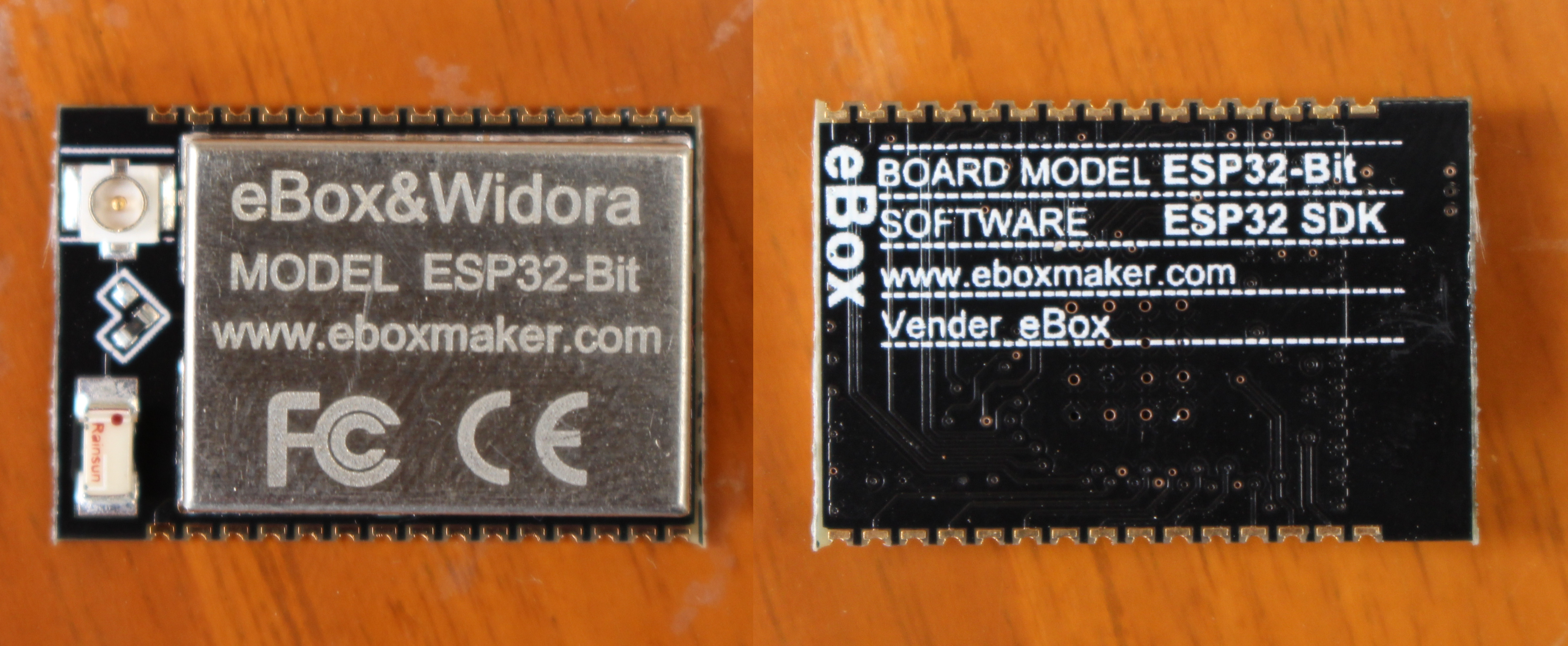
The module is apparently made by eBox, and also used in Widora board with all information (allegedly) available on eboxmaker.com website, but more on that later.
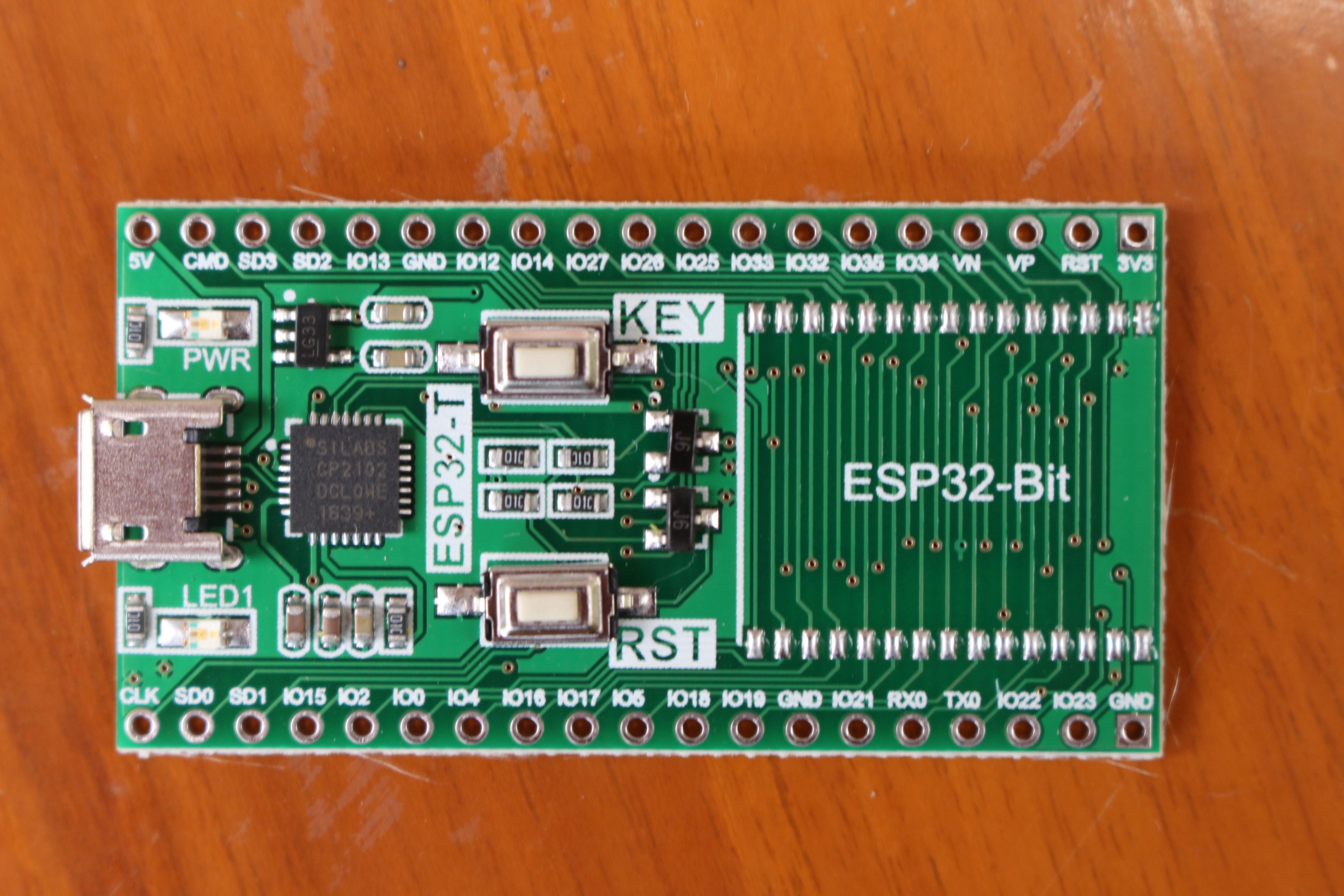
ESP32-T breakout board comes with a micro USB port for power and programming/debugging via Silabs CP2102 USB to TTL brige, a power LED, a user LED (LED1), a reset button, and a user button named “KEY”. It has two rows of 19-pin headers, and a footprint for ESP32-Bit module.
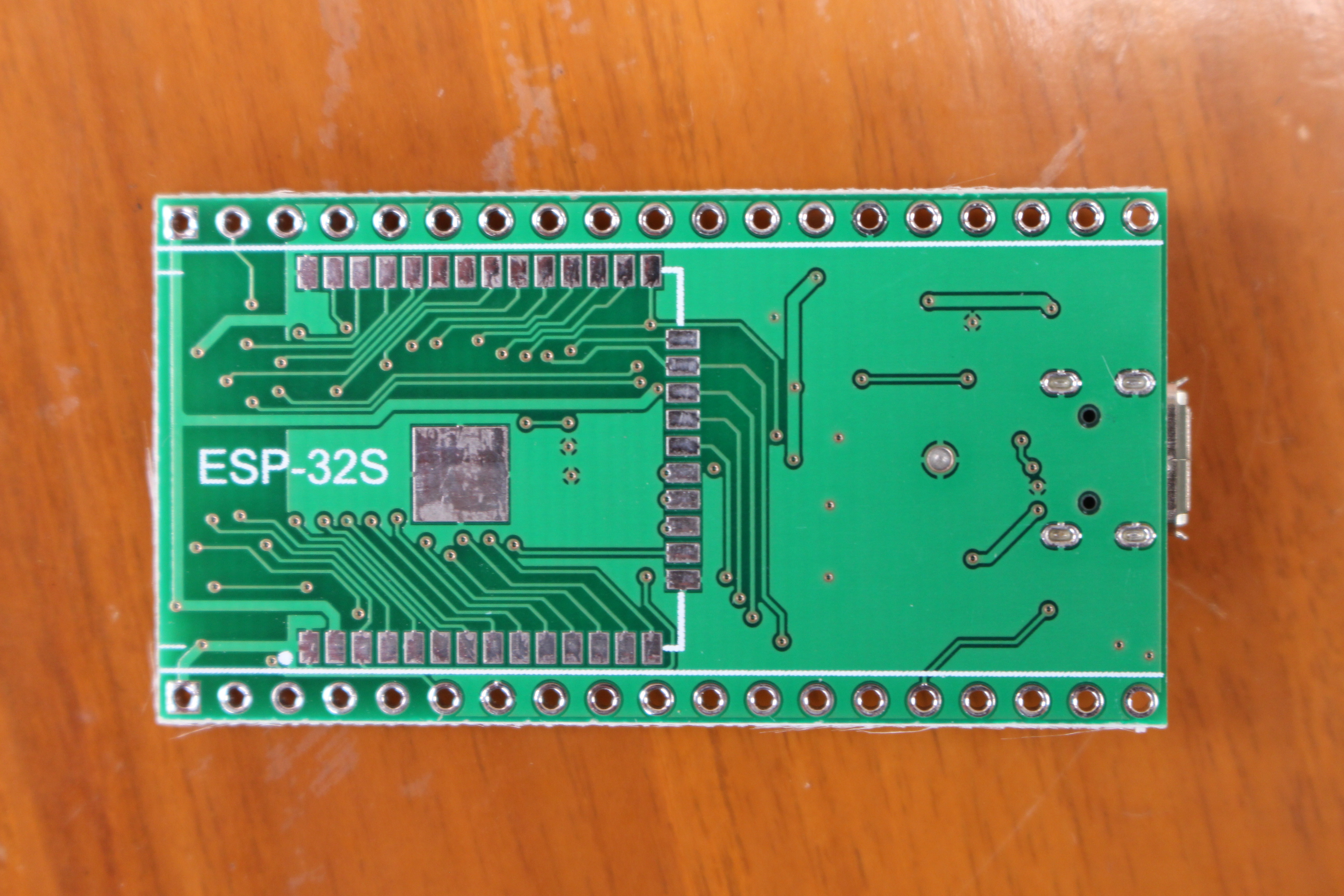
The back of the board has a footprint for ESP-32S and ESP-WROOM-32 module, which gives the board some more flexibility, as you could try it with various ESP32 modules.
Time to solder the kit. I placed ESP32-Bit on ESP32-T, and kept it in place with some black tape to solder three to four pins on each side first.
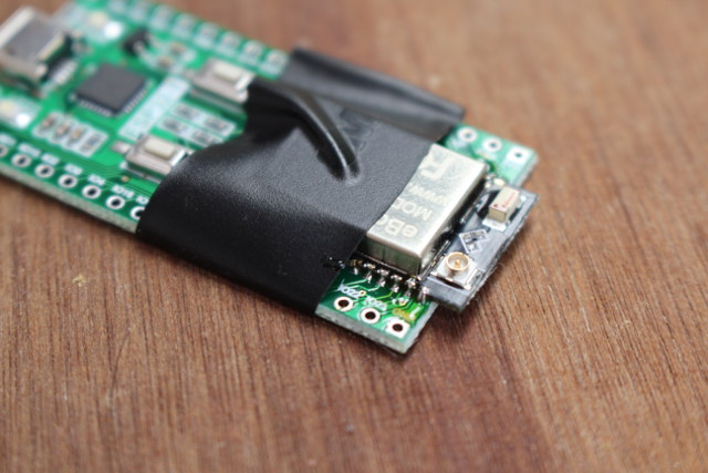
I then removed the tape, completed soldering the module, and added the headers.

The final step is to cut the excess pin on the headers, and now we can test the board which I could insert in a breadboard after pushing with some tools…
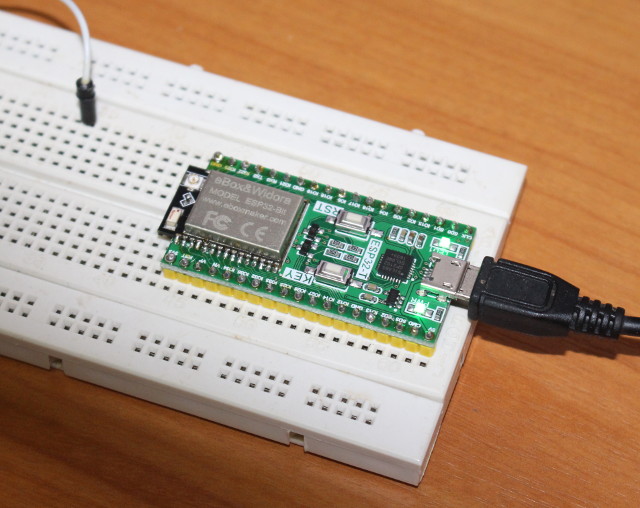 I connected a micro USB to USB between the board and my computer, and quickly I could see the PWR LED with a solid green, and LED1 blinking.
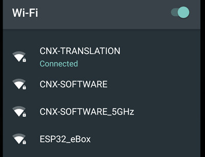
I could also see a new ESSID on my network: ESP32_eBox, and I could just input the… wait, what is the password? No idea. So I went to the board’s website, and everything is in Chinese with very limited hardware and software information on the ESP32 page. So it was basically useless, and I did not find the password, and other people neither. I asked ICStation who provided the sample, but they were unable to provide an answer before the review.
I could see the serial ouput via /dev/ttyUSB0 (115200 8N1) in Ubuntu 16.04:
|
1 2 3 4 5 6 7 8 9 10 11 12 13 14 15 16 17 18 19 20 21 22 23 24 25 26 27 28 29 30 31 |
rst:0x1 (POWERON_RESET),boot:0x13 (SPI_FAST_FLASH_BOOT) ets Jun 8 2016 00:22:57 rst:0x10 (RTCWDT_RTC_RESET),boot:0x13 (SPI_FAST_FLASH_BOOT) configsip: 0, SPIWP:0x00 clk_drv:0x00,q_drv:0x00,d_drv:0x00,cs0_drv:0x00,hd_drv:0x00,wp_drv:0x00 mode:DIO, clock div:2 load:0x3ffc0008,len:0 load:0x3ffc0008,len:1964 load:0x40078000,len:3668 load:0x40080000,len:260 entry 0x40080034 I (569) heap_alloc_caps: Initializing heap allocator: I (569) heap_alloc_caps: Region 19: 3FFC173C len 0001E8C4 tag 0 I (570) heap_alloc_caps: Region 25: 3FFE8000 len 00018000 tag 1 I (580) cpu_start: Pro cpu up. I (586) cpu_start: Starting app cpu, entry point is 0x40080be0 I (0) cpu_start: App cpu up. I (601) cpu_start: Pro cpu start user code I (625) rtc: rtc v160 Nov 22 2016 19:00:05 I (636) rtc: XTAL 40M I (842) phy: phy_version: 258, Nov 29 2016, 15:51:07, 0, 0 I (1862) cpu_start: Starting scheduler on PRO CPU. I (1269) cpu_start: Starting scheduler on APP CPU. tcpip_task_hdlxxx : 3ffc6028, prio:18,stack:2048 I (1269) wifi: frc2_timer_task_hdl:3ffc7abc, prio:22, stack:2048 I (1279) wifi: pp_task_hdl : 3ffca31c, prio:23, stack:8192 I (1929) wifi: mode : softAP (24:0a:c4:01:a4:25) dhcp server start:(ip: 192.168.4.1, mask: 255.255.255.0, gw: 192.168.4.1) hms=000:00:01 hms=000:00:02 |
Arduino core for ESP32 on ESP32-T (and Other ESP32 Boards)
But nothing really useful. Since the website mentions Arduino, I just decided to go with Arduino core for ESP32 chip released by Espressif, which explains how to use Arduino or PlatformIO IDEs. I opted to go with the Arduino IDE. The first thing is to download and install the latest Arduino IDE.
I’m running Ubuntu on my computer, so I downloaded and installed the Linux 64-bit version:
|
1 2 |
cd~ tar xvf arduino-1.8.2-linux64.tar.xz |
The next commands install the Arduino ESP32 support and dependencies:
|
1 2 3 4 5 6 7 8 9 10 |
sudo usermod -a -G dialout $USER && \ sudo apt-get install git && \ wget https://bootstrap.pypa.io/get-pip.py && \ sudo python get-pip.py && \ sudo pip install pyserial && \ mkdir -p ~/Arduino/hardware/espressif && \ cd ~/Arduino/hardware/espressif && \ git clone https://github.com/espressif/arduino-esp32.git esp32 && \ cd esp32/tools/ && \ python get.py |
We can now launch the Arduino IDE:
|
1 2 |
cd ~/arduino-1.8.2-linux64.tar.xz ./arduino |
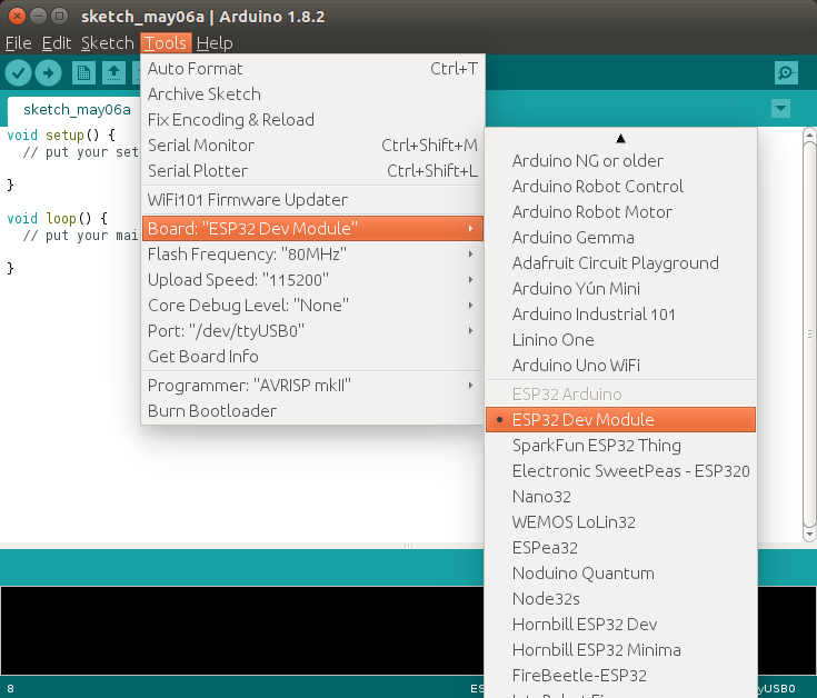
There are several ESP32 to choose from, but nothing about ESP32-T, ESP32-Bit, or Widora. However, I’ve noticed the board’s pinout looks exactly the same as ESP32Dev board shown below.
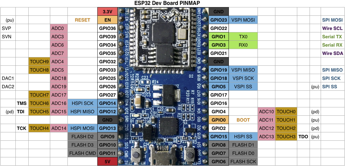
So I selected ESP32 Dev Module, and set /dev/ttyUSB0 upload speed to 115200.
The next step is to find an easy example to check if everything works, and there are bunch of those in File->Examples, Examples for ESP32 Dev Module section.

I selected GetCHIPID sample, as it just retrieve the Chip ID from the board, and as we’ll see later the Chip ID is actually the MAC Address. I could upload the code, and it indeed returned the Chip ID:
|
1 |
ESP32 Chip ID = 24A401C40A24 |
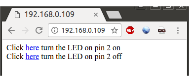
The next sample I tried – WiFi->SimpleWiFiServer – will allow you to test both WiFi connectivity and GPIOs. I modified the sketch to use pin 2 instead of pin 5 in order to control LED1 on the board connected to GPIO2. You’ll also need to set the SSID and password to connect to your WiFi network. Once you’ve compiled and uploaded the sketch to the board, you’ll need to find the board’s IP address. You can do so in your router DHCP list with the board named “espressif” by default, and the MAC address will be the same as the CHIP ID, 24-0A-C4-01-A4-24 in my case. Now you can open the web interface in a web browser to turn on and off LED1 green LED on the board.
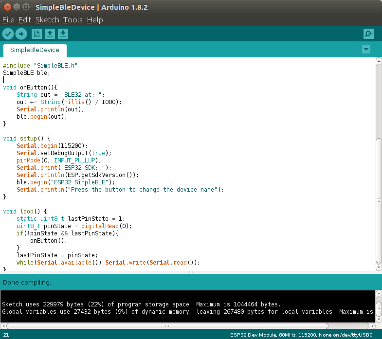
 You could also use directly http://IP_ADDRESS/H or http://IP_ADDRESS/L to pull the pin high or low. It worked beautifully, but so far, we have not done anything that does not work on the much cheaper ESP8266 boards, and I can see one Bluetooth LE code sample for ESP32 called simpleBLEDevice in Arduino IDE, so let’s try it. It will just broadcast advertise the name of the device, and change it on button press, which could be used to broadcast message to a BLE gateway.
That’s the output from the serial terminal.
|
1 2 3 4 5 6 7 8 9 10 11 12 13 14 15 |
ESP32 SDK: v2.0-rc1-443-g3cad00f-dirty BTDM CONTROLLER VERSION: 010101 btip start copy .data from 4000d890 to 3ffae6e0, len 00001830 set .bss 0x0 from 3ffb8000 to 3ffbff70, len 00007f70 BTDM ROM VERSION 0101 BD_ADDR: 24:0A:C4:01:A4:26 NVDS MAGIC FAILED RF Init OK with coex Enable Classic BT Enable Low Energy Press the button to change the device name BLE32 at: 102 BLE32 at: 316 BLE32 at: 317 |
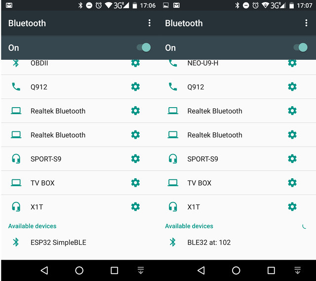
The initial name is ESP32 SimpleBLE, and as I press the KEY button on the board, the name will change to “BLE32 at: xxx”. I could detect a Bluetooth ESP32 device with the various names with my Android smartphone.
Since, it’s just advertising the name, there’s no pairing. But that’s a start. To have more insights into Bluetooth, you may also want to check out WiFiBlueToothSwitch.ino sample which shows show to use various mode such as Bluetooth only, Bluetooth + WiFi, WiFi STA, etc… For a more practical use of Bluetooth on ESP32, Experiments with Bluetooth and IBM Watson article may be worth a read. But a faster dual core processor and Bluetooth support are not the only extra features of ESP32 compared to ESP8266, as you also get more GPIOs, hardware PWM, better ADC, a touch interface, a CAN bus, Ethernet, etc…, so there’s more to explore, although I’m not sure all features are fully supported in ESP-IDF SDK and Arduino.
Final Words about ESP32-T and ESP32-Bit
After some initial difficulties, and confusions, I managed to make ESP32-T development kit work, but it’s difficult to recommend it. First, documentation is really poor right now, and while I found out you can use the exact same instructions than for ESP32Dev board, it does not reflect well on the company. Second, the board is sold as a kit that needs to be soldered, which may be a hassle for many, and possibly a fun learning experience for a few. Finally, ESP32-T + ESP32-Bit sells for $15 to $20 on various website, which compares to competitors fully assembled development boards – such as Wemos LoLin32 – now going for less than $10 shipped, and which basically the same features set (ESP32 + 4MB flash) minus the user LED and button, and a u.FL connector for an external antenna.
I’d still like to thank ICStation for giving me the opportunity to test the board. They are now selling it for $14.99 shipped with 15% extra discount possible with Jeanics coupon (for single order). You’ll also find ESP32-T board on Aliexpress, but pay close attention if you are going to buy there, as it may be sold without ESP32-Bit module. Usually, all prices well below $10 are without the module.

Jean-Luc started CNX Software in 2010 as a part-time endeavor, before quitting his job as a software engineering manager, and starting to write daily news, and reviews full time later in 2011.
Support CNX Software! Donate via cryptocurrencies, become a Patron on Patreon, or purchase goods on Amazon or Aliexpress