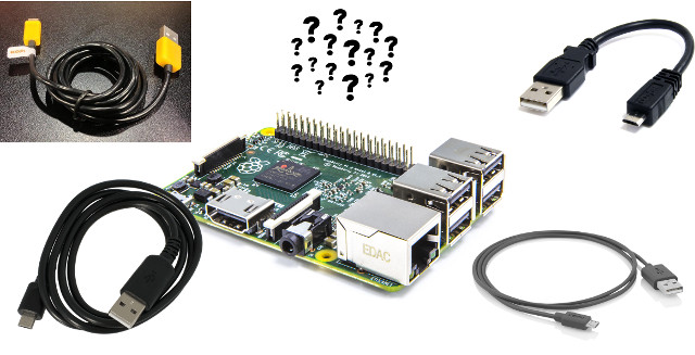
Yesterday one person contacted me on Facebook asking me whether there was any chance of me doing a “which usd-micro usb cable is best”, as there’s not much clear information on the Internet. His purpose was to charge his phone, but many development boards come with a micro USB port, and I’ve read many comments about powering the board. It also happened to me, and the main cause can either be the power supply which does not work as rated (usually 5V/2A), or the micro USB cable which may have a resistance a little to high leading to voltage drops. You’ll know you may have a power problem when the board refuses to boot, and usually boot loop, or randomly reboots especially under high load. The first solution is to get a power supply that provide the right voltage and amperage, and you can test that with USB Charger doctor an ultra cheap tool that will show both the voltage and intensity on an LCD display, although it will only work on chargers with a USB port.
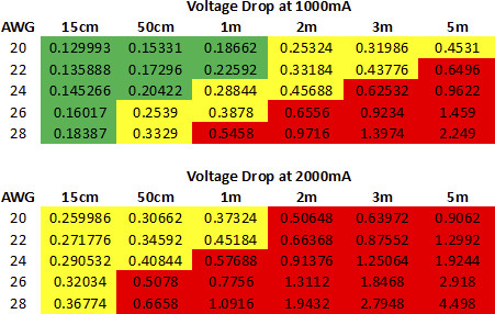
 But what about the micro USB cable? Let’s consider the actual problem, which is well explained in a post about USB cable resistance, but I’ll summarize below. First all conductor have some tiny resistance, and usually the thicker the cable the less resistance there is. The American Wire Gauge (AWG) value is often used to describe the thickness of the cable, with numbers from 0 to 40 ranging from the larger diameter/smaller resistance/higher capacity to the smaller diameter/larger resistance/lower capacity. For USB cable, AWG20 to AWG28 are often used for USB cables, and the latter seems to be very common for data wires, but what matters here is the AWG value for the power wires (5V/GND) of the cable. The resistance also depends on the length of the cable with longer cables having a longer resistance, as well as the USB contact resistance, but I’m not sure we can do much about that one. Anyway, that means a short cable with a lower AWG value would be better suited here, as shown in the table below from the aforelinked post using 5V/1A and 5V/1A loads. This table assumes 30 mOhms contact resistance, so the values would be lower if there’s a lower resistance.
Boards can normally work in a range around 5V. For the sake of argument, let’s assume a board taking 4.5V to 5.5V DC input. and would reboot if the voltage drops below 4.5V. If you have a 5V power supply use with a non-optimal AWG rating and length, the voltage will drop more than 0.5V (red zone above) and the board will not work properly. 5V/1A (5W) is a very common on development boards, while getting to 10Watts is possible for you’d need a high load plus possible some USB storage device to reach the power level.
Based on those results, what we want is an AWG20 cable (ideally) with a length of less than one meter, and the shorter the better. So I’ve been looking for such cables on the web and found a bunch. I did not test any, but they may be good candidates to look at:
- KoPI 20AWG micro USB cable selling for $5.99 on Newegg.
- 5x Tronsmart micro USB cables for $8.49 shipped: 1x 6 feet (not ideal), 3x 3.3 feet (~1 meter), 1x 1 foot (33 cm).
- 35 cm micro USB cable (AWG20) for $2.99 shipped on eBay. It can also be found on Aliexpress for $2.49.
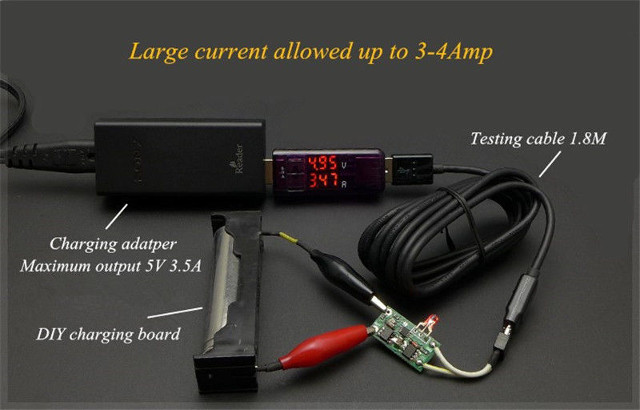
There are many others, just search for AWG20 micro USB cable, or in some cases micro USB charging cables, and you should find decent cables that should not cause power or charging troubles. The last cable in the list above (eBay) was tested with a Charger Doctor dongle showing 4.95V/3.47A going through the cable (1.8 meter length). The voltage value should be lower when measured at the DIY charging board due the internal resistance of the cable, but it still shows the cable allows around 3 to 4 amps.

Jean-Luc started CNX Software in 2010 as a part-time endeavor, before quitting his job as a software engineering manager, and starting to write daily news, and reviews full time later in 2011.
Support CNX Software! Donate via cryptocurrencies, become a Patron on Patreon, or purchase goods on Amazon or Aliexpress


