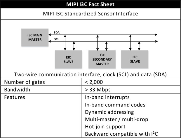
MIPI I3C Sensor Interface is a Faster, Better, Backward Compatible Update to I2C Protocol
I2C (Inter-Integrated Circuit) is one of the most commonly used serial bus for interfacing sensors and other chips, and use two signals (Clock and Data) to control up to 128 chips thanks to its 7-bi address scheme [Update: That’s the theory, as in practice it’s limited to a dozen devices max. due to capacitive load, see comments]. After announcing it was working of a new I3C standard in 2014, the MIPI Alliance has now formally introduced the MIPI I3C (Improved Inter Integrated Circuit) Standardized Sensor Interface, a backward compatible update to I2C with lower power consumption, and higher bitrate allowing it to be used for applications typically relying on SPI too.
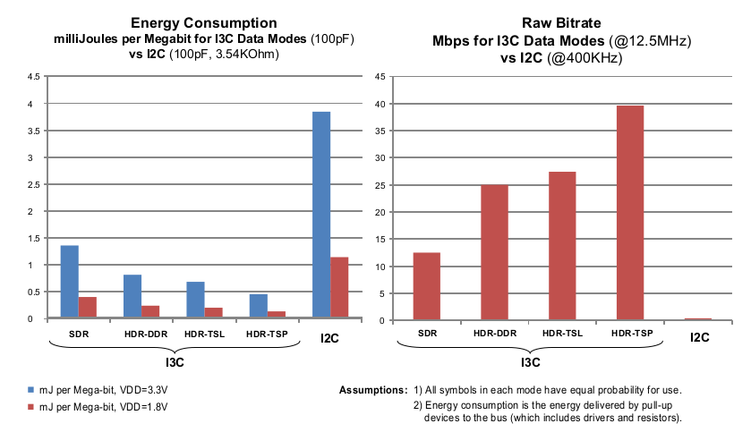
I3C offers four data transfer modes that, on maximum base clock of 12.5MHz, provide a raw bitrate of 12.5 Mbps in the baseline SDR default mode, and 25, 27.5 and 39.5 Mbps, respectively in the HDR modes. After excluding transaction control bytes, the effective data bitrates achieved are 11.1,20, 23.5 and 33.3 Mbps.
MIPI I3C vs I2C Energy Consumption and Bitrate – Click to Enlarge
The MIPI Alliance has also provided a table comparing I3C, I2C, and SPI features, advantages and disadvantages.
Parameter
MIPI I3C
I2C
SPI
Number of Lines
2-wire
2-wire (plus separate wires for each required interrupt signal)
4-wire (plus separate wires for each required interrupt signal)
Effective Data Bitrate
33.3 Mbps max at 12.5 MHz
(Typically: 10.6 Mbps at 12 MHz SDR)
3 Mbps max at 3.4 MHz (Hs)
0.8 Mbps max at 1 MHz (Fm+)
0.35 Mbps max at 400 KHz (Fm)
Approx. 60 Mbps max at 60 MHz for conventional implementations (Typically: 10 Mbps at 10 MHz)
Advantages
Only two signal lines
Legacy I2C devices co-exist on the same bus (with some limitations)
Dynamic addressing and supports
static addressing for legacy I2C
devices
I2C-like data rate messaging (SDR)
Optional high data rate messaging
modes (HDR)
Multi-drop capability and dynamic
addressing avoids collisions
Multi-master capability
In-band Interrupt support
Hot-join support
A clear master ownership and
handover mechanism is defined
In-band integrated commands
(CCC) support
Only two signal lines
Flexible data transmission rates
Each device on the bus is
independently addressable
Devices have a simple master/slave relationship
Simple implementation
Widely adopted in sensor
applications and beyond
Supports multi-master and multi-drop capability features
Full duplex communication
Push-pull drivers
Good signal integrity and high speed below 20MHz (higher speed are challenging)
Higher throughput than I2C and SMBus
Not limited to 8-bit words
Arbitrary choice of message size, content and purpose
Simple hardware interfacing
Lower power than I2C
No arbitration or associated failure modes
Slaves use the master’s clock
Slaves do not need a unique address
Not limited by a standard to any maximum clock speed (can vary between SPI devices)
Disadvantages
Only 7-bits are available for device addressing
Slower than SPI (i.e. 20Mbps)
New standard, adoption needs to be proven
Limited number of devices on a
bus to around a dozen devices
Only 7-bits (or 10-bits) are available for static device addressing
Limited communication speed rates and many devices do not support the higher speeds
Slaves can hang the bus; will require
system restart
Slower devices can delay the
operation of faster speed devices
Uses more power than SPI
Limited number of devices on a bus
to around a dozen devices
No clear master ownership and
handover mechanism.
Requires separate support signals for
interrupts
Need more pins than I2C/MIPI I3C
Need dedicated pin per slave for
slave select (SS)
No in-band addressing
No slave hardware flow control
No hardware slave acknowledgment
Supports only one master device
No error-checking protocol is
defined
No formal standard, validating
conformance is not possible
SPI does not support hot swapping
Requires separate support signals
for interrupts
You’ll find more technical details by downloading MIPI I3C specifications and/or whitepaper (free email registration required). Note that only MIPI member can have access to the complete specifications.
Jean-Luc started CNX Software in 2010 as a part-time endeavor, before quitting his job as a software engineering manager, and starting to write daily news, and reviews full time later in 2011.
This website uses cookies to improve your experience. We'll assume you're ok with this, but if you don't like these, you can remove them Accept
Privacy & Cookies Policy
Privacy Overview
This website uses cookies to improve your experience while you navigate through the website. Out of these, the cookies that are categorized as necessary are stored on your browser as they are essential for the working of basic functionalities of the website. We also use third-party cookies that help us analyze and understand how you use this website. These cookies will be stored in your browser only with your consent. You also have the option to opt-out of these cookies. But opting out of some of these cookies may affect your browsing experience.
Necessary cookies are absolutely essential for the website to function properly. This category only includes cookies that ensures basic functionalities and security features of the website. These cookies do not store any personal information.
Any cookies that may not be particularly necessary for the website to function and is used specifically to collect user personal data via analytics, ads, other embedded contents are termed as non-necessary cookies. It is mandatory to procure user consent prior to running these cookies on your website.

 I3C offers four data transfer modes that, on maximum base clock of 12.5MHz, provide a raw bitrate of 12.5 Mbps in the baseline SDR default mode, and 25, 27.5 and 39.5 Mbps, respectively in the HDR modes. After excluding transaction control bytes, the effective data bitrates achieved are 11.1,20, 23.5 and 33.3 Mbps.