Getting Started with Pine64 PADI IoT Stamp – Part 2: Serial Console, GCC SDK, Flashing & Debugging Code
PADI IoT Stamp module powered by Realtek RTL8710AF ARM Cortex M3 WiFi SoC is a potential competitor to Espressif ESP8266 modules. Pine64, the manufacturer of the module, sent me their kit with a $2 IoT stamp, a breakout board, a USB to TTL debug board and a J-Link debug board. In the first part of the review I’ve shown the hardware and how to assemble PADI IoT stamp kit. In the second part I’m going to write a tutorial / getting start guide showing how to control the board with AT commands, build the firmware with GCC SDK, and finally demonstrate how to flash and debug the firmware with the J-Link debugger.
The Quick Start Guide indicates you need to connect the USB to TTL debug board to UART2 instead of UART1 as I did on the very similar B&T RTL-00 RTL8710AF module, and set connection settings to 38400 8N1. This did not work for me, and I had indeed to connect the USB to TTL board to UART0 instead (GB0 & GB1 pins).
Click to Enlarge
I’ll be using a Ubuntu 16.04 (Linux) computer for this quick start guide, but you can work with Windows and Mac OS X too, as tools as available for all three operating systems. So in my case I configure minicom to 38400 8N1 using /dev/ttyUSB0 device, and the boot log is almost the same as B&T RTL-00 with the same ROM version and toolchain:
There are however some changes, and for example the firmware used on PADI IoT Stamp has slightly more heap available. The guide also mentions ATS? should show all command available, but it’s not working for me:
1
2
3
4
5
6
# ATS?
[MEM]After docmd,available heap60656
#
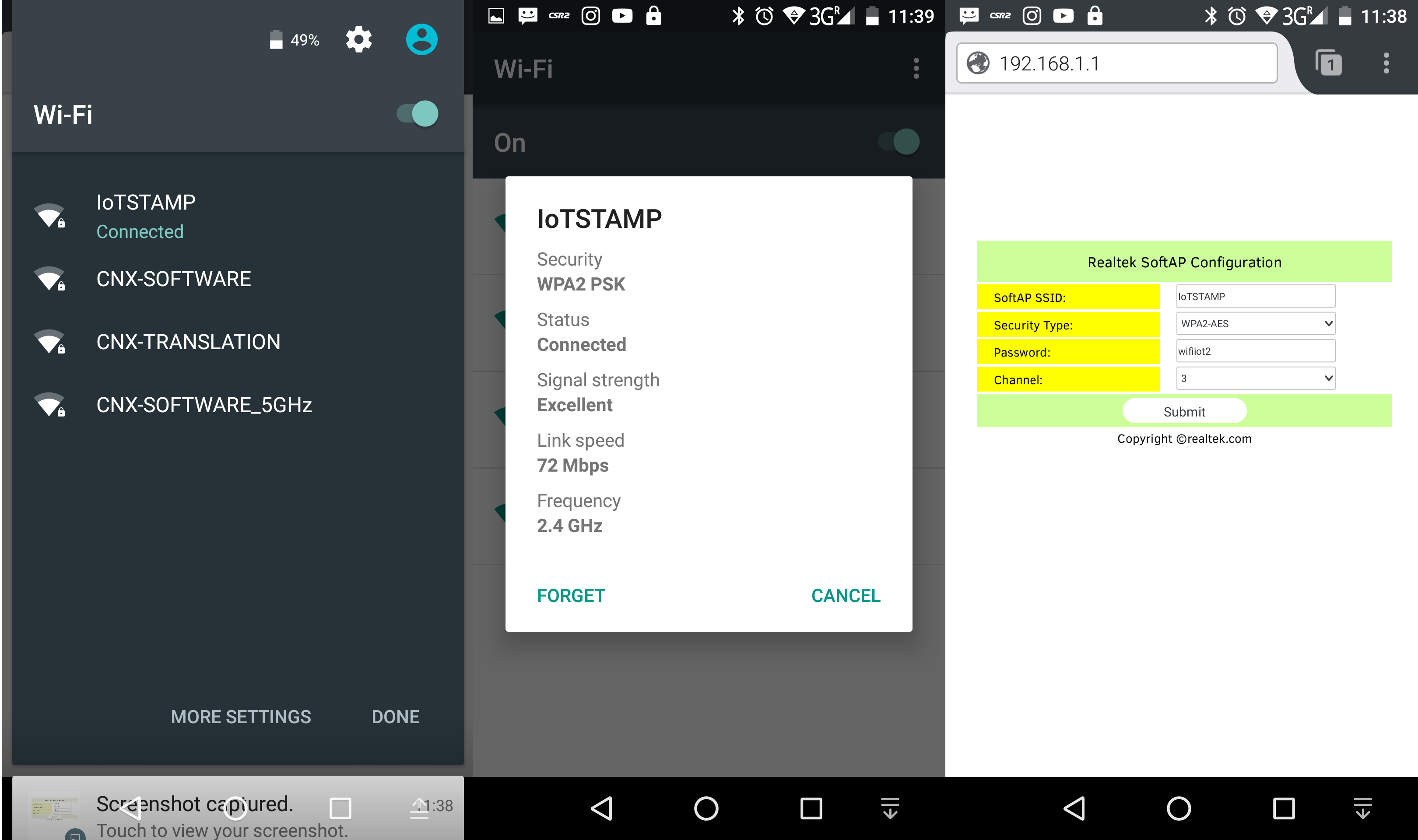
Typing “help” as I did with RTL-00 module does not work either, and that does not look since documentation appears to be wrong again, but that’s not a big deal since we have all AT commands listed in that document. I could configure it as “IoTSTAMP” access point:
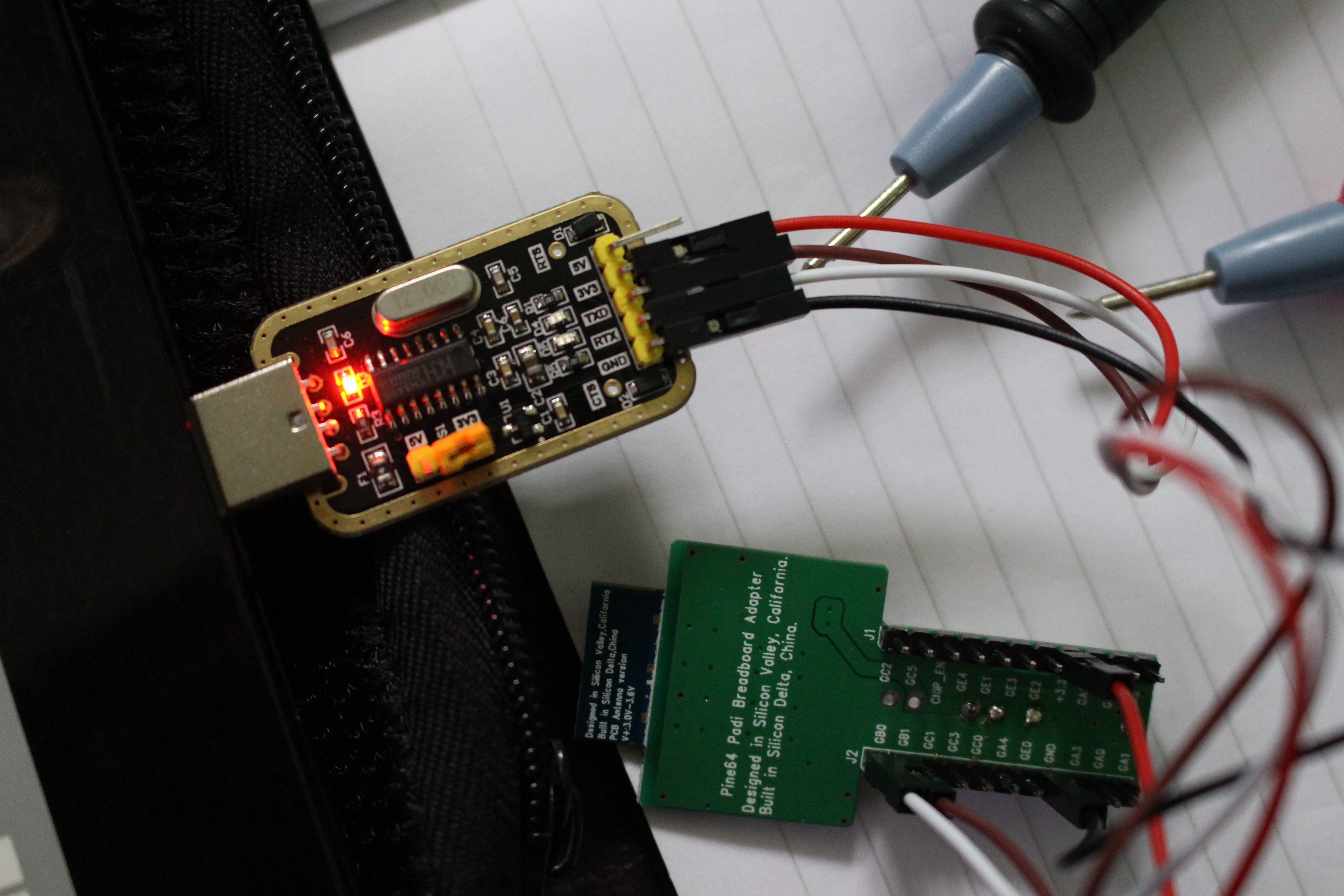
I did not connect an LED, but instead measured the value with multimeter and could confirm the voltage level was right in both cases.
B&T provided an SDK which required a an unlicensed / pirated version of IAR ARM Workbench, but Pine64/Realtek have released a GCC SDK that do you require you to use pirated software. You can download sdk-ameba-rtl8710af-v3.5a_without_NDA_GCC_V1.0.0 (198 MB) directly from Pine64 website. After unzipped the SDK you can enter sdk-ameba-rtl8710af-v3.5a_without_NDA_GCC_V1.0.0 directory, and open readme.txt to have a look at RTL8710 GCC SDK structure:
Since I only aim to write a getting started guide I won’t go through all of it, but we can see the low level source code & binary, some documentation, an example project, and some tools include Android and iOS apps, OTA download server and more.
Nevertheless the readme.txt tells us to first read “UM0096 Realtek Ameba-1 build environment setup – gcc.pdf” in order to setup our development environment. The instructions are available with Windows and Linux, but again I’m only test them using Ubuntu 16.04. They’ll be very similar since you’ll rely on cygwin in Windows, and if you run the latest Windows 10 you should be able to install Windows subsystem for Linux, and use the Linux instructions.
First you have to make sure some tools and libraries are installed:
1
sudo apt install build-essential gawk bc libc6-dev:i386 lib32ncurses5-dev
then we can build the sample project:
1
2
cd project/realtek_ameba1_va0_example/GCC-RELEASE/
make
If everything goes well the log should end showing “Image manipulating” as follows:
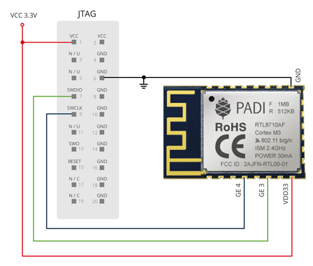
There’s also an ota.bin image which might be usable using OTA firmware update documentation, but for this guide I want to use the J-Link debugger that the company sent me instead. The GCC SDK is not for PADI IoT stamp, but instead for Realtek Ameba Arduino board, and you’ll be asked to connect the board through one of the micro USB port. That won’t work with IoT stamp since there’s no USB port at all, and instead you’ll need to go and back forth between multiple documentation, and connect the board as per the JTAG/SWD connections diagram shown below.
That document also mentions that:
Required external power VCC 3.3V, JTAG/SWD didn’t supply power to the PADI IoT Stamp, VCC connection from PADI IoT Stamp is used by JTAG/SWD as voltage reference only.
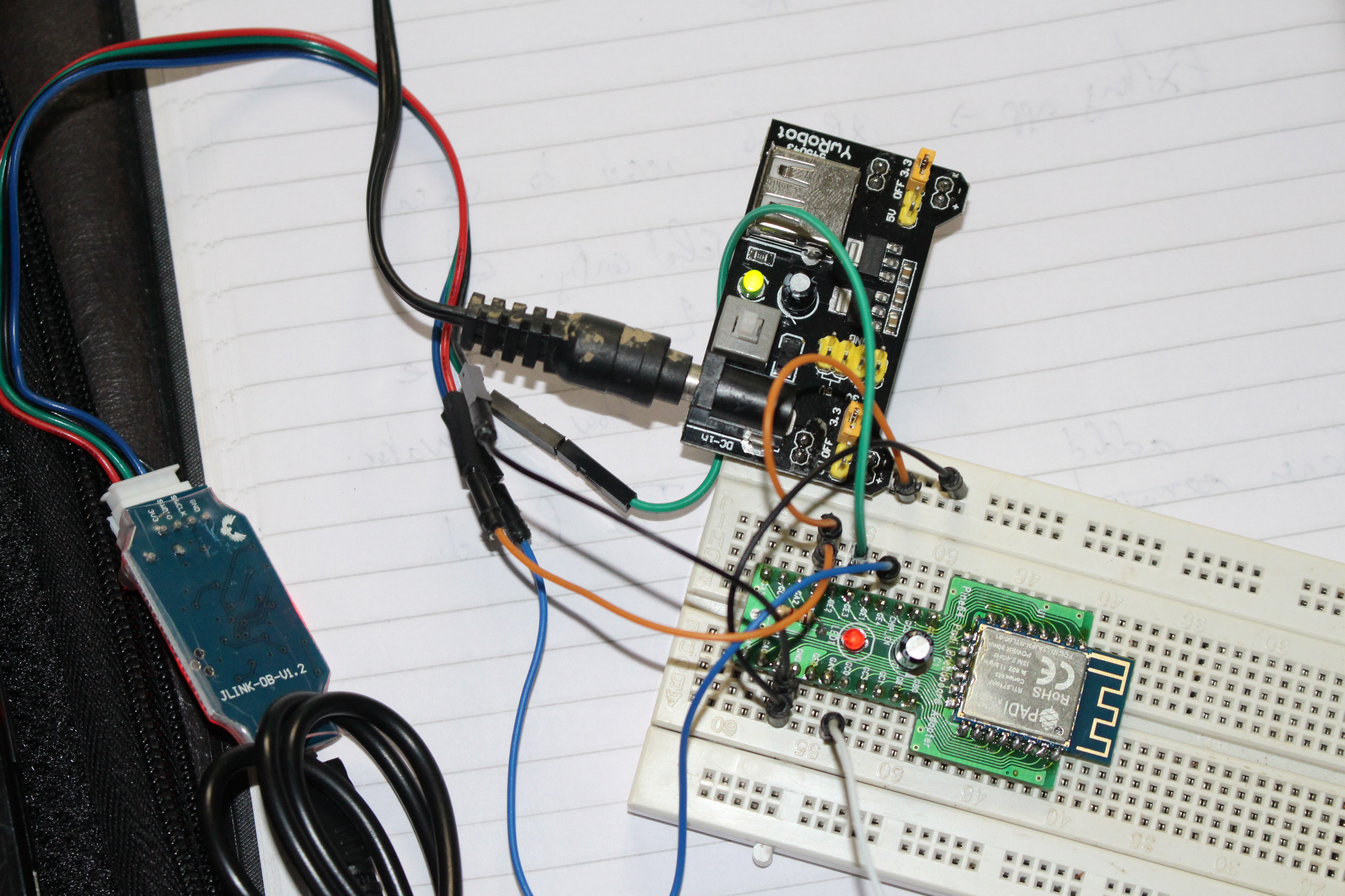
At first, I did not see that, and used it without external power supply, but since I was not successful with the J-Link debugger (for another reason), so I ended up inserting PADI IoT stamp into a breadboard and added Ywrobot power board to provide an external 3.3V power source.
There are two sets of instructions in UM96 document to download and flash the code: OpenOCD/CMSIS-DAP and JLink, so since I had a J-Link debugger, I went with that latter. First you have to download J-Link Software and Documentation pack and for my system I selected ” Linux, DEB Installer, 64-bit V6.12″. After accepting the EULA, I got JLink_Linux_V612_x86_64.deb file which I installed as follows:
1
sudo dpkg-iJLink_Linux_V612_x86_64.deb
Now we can start JLink GBD server for a Cortex-M3 as explained in the document:
So the JLink debugger is detected, but failed to connect to the target. Apart from the last error, everything looks exactly as in the documentation. That’s when I started to add an external power boar, solder the capacitor, and double check my connection. But finally after many trials and errors, I realized that I had to use a SWD connection (SWCLK/SWDIO signals) instead of JTAG…
Now keep the GDB server running, open a new terminal windows in the same directory (where you’ve built the code), and run make flash to download and flash the code to the board:
Thisisfree software:you are free tochange andredistribute it.
There isNO WARRANTY,tothe extent permitted by law.Type"show copying"
and"show warranty"fordetails.
ThisGDB was configured as"--host=i686-linux-gnu --target=arm-none-eabi".
Forbug reporting instructions,please see:
<http://www.gnu.org/software/gdb/bugs/>.
0x1001bbcein??()
Notification of completion forasynchronous execution commands isoff.
Resets the core only,notperipherals.
Sleep20ms
Breakpoint1:file../src/main.c,line18.
[Switching toThread57005]
Breakpoint1,main()at../src/main.c:18
18console_init();
(gdb)list
13*@retval None
14*/
15voidmain(void)
16{
17/* Initialize log uart and at command service */
18console_init();
19
20/* pre-processor of application example */
21pre_example_entry();
22
At this point, you’ll just need to use gdb command out of the scope of this post, but you can find tutorials online, for example this. You can also run make ramdebug in order to write ram_all.bin to RAM then enter gdb debug.
So that’s only the debug part, but if you want to create your own application, you’ll need to study the source code, and there are plenty of examples to help you in project/realtek_ameba1_va0_example/example_sources folder:
Note that this is only useful is you want to use PADI IoT stamp as a standalone module, and if you connect it to another board (e.g. Arduino) you can control it through the AT command set.
So while PADI IoT stamp is a usable platform with its GCC SDK, currently documentation is not always correct, and development should be reserved to experienced developers, as it’s not exactly as straightforward as Arduino, Lua or other firmware often used in ESP8266. Arduino will most likely never supported on IoT stamp due to memory constraints, but mbed support should come to the module in the first part of next year, which will make everything much easier.
If you want to play with your own, you can get PADI IoT stamp for $1.99, the breakout board kit for $0.5, the USB to serial debug board for $1.99, and the JLink (SWD) debugger is $7.99 on Pine64 online store. Please note that the two debug boards are standard components, so you may use your own, if you already have such hardware.
Jean-Luc started CNX Software in 2010 as a part-time endeavor, before quitting his job as a software engineering manager, and starting to write daily news, and reviews full time later in 2011.
This website uses cookies to improve your experience. We'll assume you're ok with this, but if you don't like these, you can remove them Accept
Privacy & Cookies Policy
Privacy Overview
This website uses cookies to improve your experience while you navigate through the website. Out of these, the cookies that are categorized as necessary are stored on your browser as they are essential for the working of basic functionalities of the ...
Necessary cookies are absolutely essential for the website to function properly. This category only includes cookies that ensures basic functionalities and security features of the website. These cookies do not store any personal information.
Any cookies that may not be particularly necessary for the website to function and is used specifically to collect user personal data via analytics, ads, other embedded contents are termed as non-necessary cookies. It is mandatory to procure user consent prior to running these cookies on your website.

 That document also mentions that: