After I posted about PADI IoT Stamp IoT kit based on RTL8710AF ARM Cortex M3 WiSoC yesterday, I was soon asked whether I could compare the RF performance against ESP8266 modules like ESP-12. I don’t have any equipment to do this kind of test, except for some simple test like testing range with WiFi Analyzer app, but I remember Pine64 told me they had some comparison data a little while, and accepted to share their results.
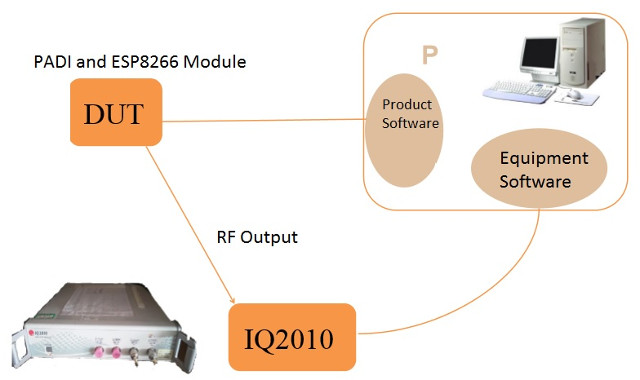
 The test setup is comprised of Litepint IQ2010 multi-communication connectivity test system and PC software, as well as the device under test (DUT) with PADI IoT Stamp (version with u.FL antenna connector) and ESP-07 ESP8266 module as a u.FL connector is required to connect the test system.
They’ve tested 802.11b, 802.11g, and 802.11n, but for IoT projects 802.11b is the most important as usually long range is more important than data rate. Test results below are based on CH1 input data with 1dBm compensation.
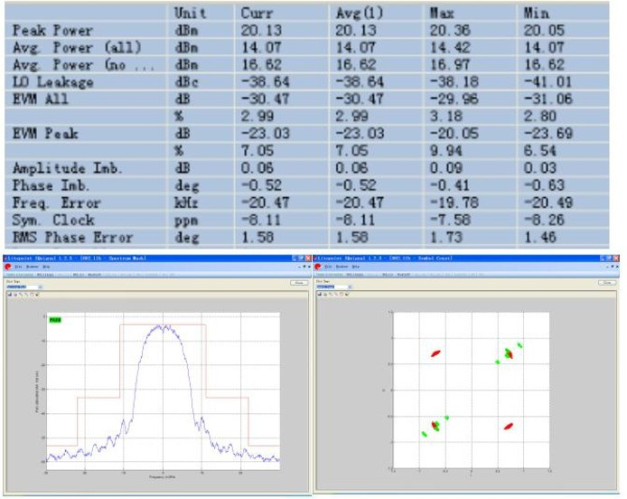
That’s the results for ESP8266…

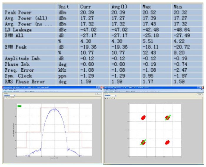
.. and the results for RTL8710 using an 802.11b connection.

The tables show peak and average power, LO leakage, EVM (Error vector magnitude), Frequency error and other parameters. The spectral mask, and constellation diagram are also shown for each case. If you’ve never studied or worked about RF signal, it’s quite all complicated, but can get some insights by reading Practical Manufacturing Testing of 802.11 OFDM Wireless Devices white paper.
A Spectral Mask describes the distribution of signal power across each channel. When transmitting in a 20 MHz channel, the transmitted spectrum must have a 0 dBr bandwidth not exceeding 18 MHz, –20 dBr at 11 MHz frequency offset, –28 dBr at 20 MHz frequency offset, and the maximum of –45 dBr and –53 dBm/MHz at 30 MHz frequency offset and above.
The Constellation Diagram is a representation of a signal modulated by a digital modulation scheme. It is useful to identify some types of corruption in signal quality. The EVM is a measure of the deviation of the actual constellation points from the ideal error-free locations in the constellation diagram (in % RMS or dB), and you’d want to keep this as small as possible.
In both diagrams, it appears that the signal is quite cleaner on PADI IoT stamp compared to ESP8266 module with more distortions. The diagram are not quite clear enough to check the Spectral Mask values. I’m sure we’ll get some more feedback in the comments section.
If you are interested in 802.11g and 802.11n results, you can access the rest of the report.

Jean-Luc started CNX Software in 2010 as a part-time endeavor, before quitting his job as a software engineering manager, and starting to write daily news, and reviews full time later in 2011.
Support CNX Software! Donate via cryptocurrencies, become a Patron on Patreon, or purchase goods on Amazon or Aliexpress


