Back in September, Pine64 unveiled their $2 PADI IoT Stamp based on Realtek RTL8710 ARM Cortex M3 WiFi SoC aiming to compete with Expressif ESP8266 solutions. The company has now sent me their complete kit for review, which beside the module itself includes a breakout board kit, and some hardware debug tools. In the first part of the review, I’ll check out the hardware, and solder the kit.
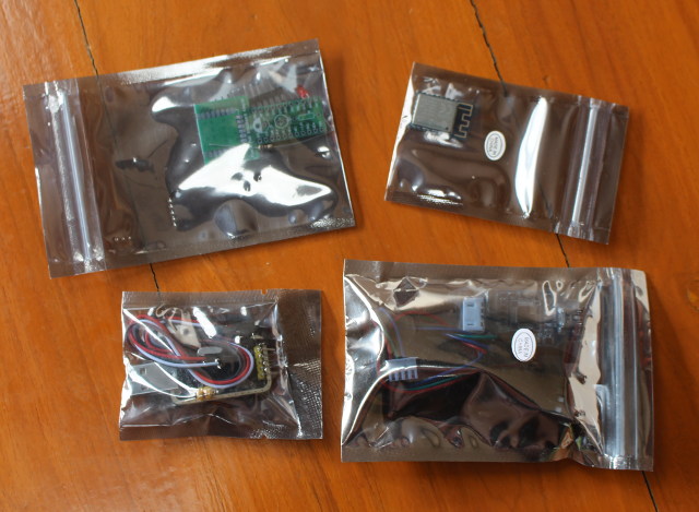
I received a package with four antistatic bags.
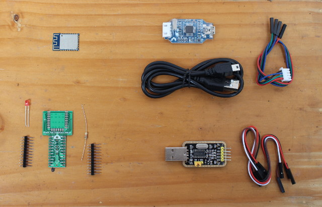
From top left to bottom right, we have PADI IoT Stamp, JLINK-OB debugger based on an STM32 MCU with some jumper wires (aka Dupont cables) for SWD signals, and a USB cable to your computer in order to flash the firmware or do some bare metal programming, a breakout board kit including two headers, a RED LED, and a resistor, and finally a USB to Serial board based on CH340G with 4 jumper wires for Tx, Rx, GND and 3.3V to access the serial console.
PADI IoT stamp looks very similar to B&T RTL-00 RTL8710AF board so I compared both board side-by-side.
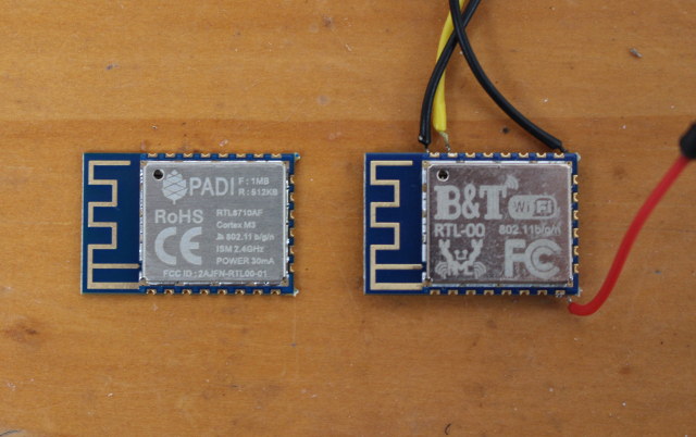
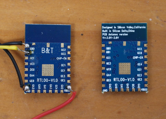
So it’s 100% clear the PCB is exactly the same, but I’ve been told the module has some differences which may make PADI IoT stamp firmware incompatible with other Realtek RTL8710 modules such as B&T RTL00. The bottom of PADI IoT stamp board indicates it’s the PCB antenna version, because a u.FL antenna version is also planned, and it should look like B&T RTL01. Pine64 RTL8710 module cover also has some more details like the amount of flash (1MB) and RAM (512KB), as well as the FCC-ID number: 2AJFN-RTL00-01 which has been applied by B&T (Zhongshan Boantong Communication Technology Co. , Ltd).
It’s not really fun to use the module standalone as you’d need to solder the wire one by one as I did for B&T RTL00, so unless you have already made your own custom board for the module, the first thing you’ll want to do is to solder PADI IoT module, headers, and passive components “Pine64 Padi Breadboard Adapter”.
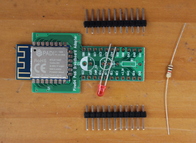
I’ve started by soldering PADI IoT Stamp, and used some sticky tape first to solder the first few points, then I went to solder the LED (make sure to use the right polarity) and the resistor, and finally I inserted the two headers into a breadboard, and inserted the module in order to complete the soldering. You can ignore C1 capacitor as it’s not provided, nor needed. You’ll need to solder your own C1 capacitor to prevent issues with WiFi.
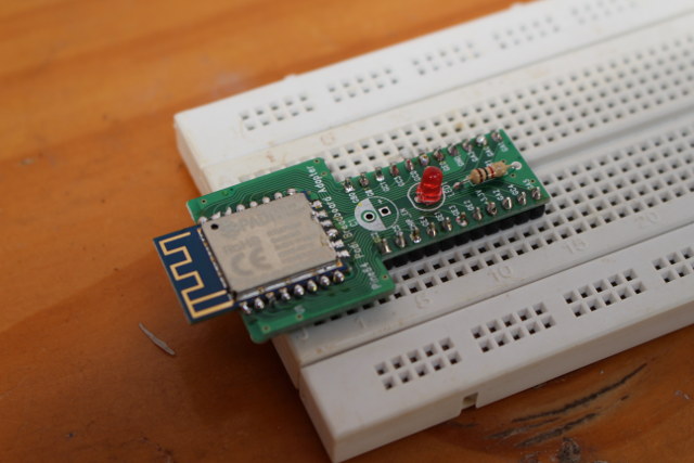
That’s fun to do, and not too hard to do, but I’d assume many people would rather just have everything already soldered, but it’s not available yet. Once it’s done you just need to provide 3.3V and GND to power the board.
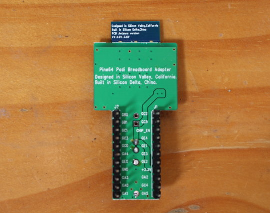
That’s all I’ve done today. For the second part of the review, I’ll most probably skip the AT commands set since it should be very similar to that I did in my Realtek RTL8710 getting started guide, albeit possibly with some various to the exact command. So instead, I’ll likely try to play with the JLink debugger, and their RTL8710 GCC SDK, or mbed 5.0 SDK, if the latter is released at the time of the review.
Pine64 has kept everything very inexpensive, as beside the $1.99 PADI IoT stamp, the breakout board kit is only $0.5, the USB to serial debug board is $1.99, and the JLink debugger is $7.99. You may not even need the last two if you already have such tools. All items can be purchased on Pine64 online store, and shipping should add between $7 and $12.
Continue reading “Getting Started with Pine64 PADI IoT Stamp – Part 2: Serial Console, GCC SDK, Flashing & Debugging Code“.

Jean-Luc started CNX Software in 2010 as a part-time endeavor, before quitting his job as a software engineering manager, and starting to write daily news, and reviews full time later in 2011.
Support CNX Software! Donate via cryptocurrencies, become a Patron on Patreon, or purchase goods on Amazon or Aliexpress


