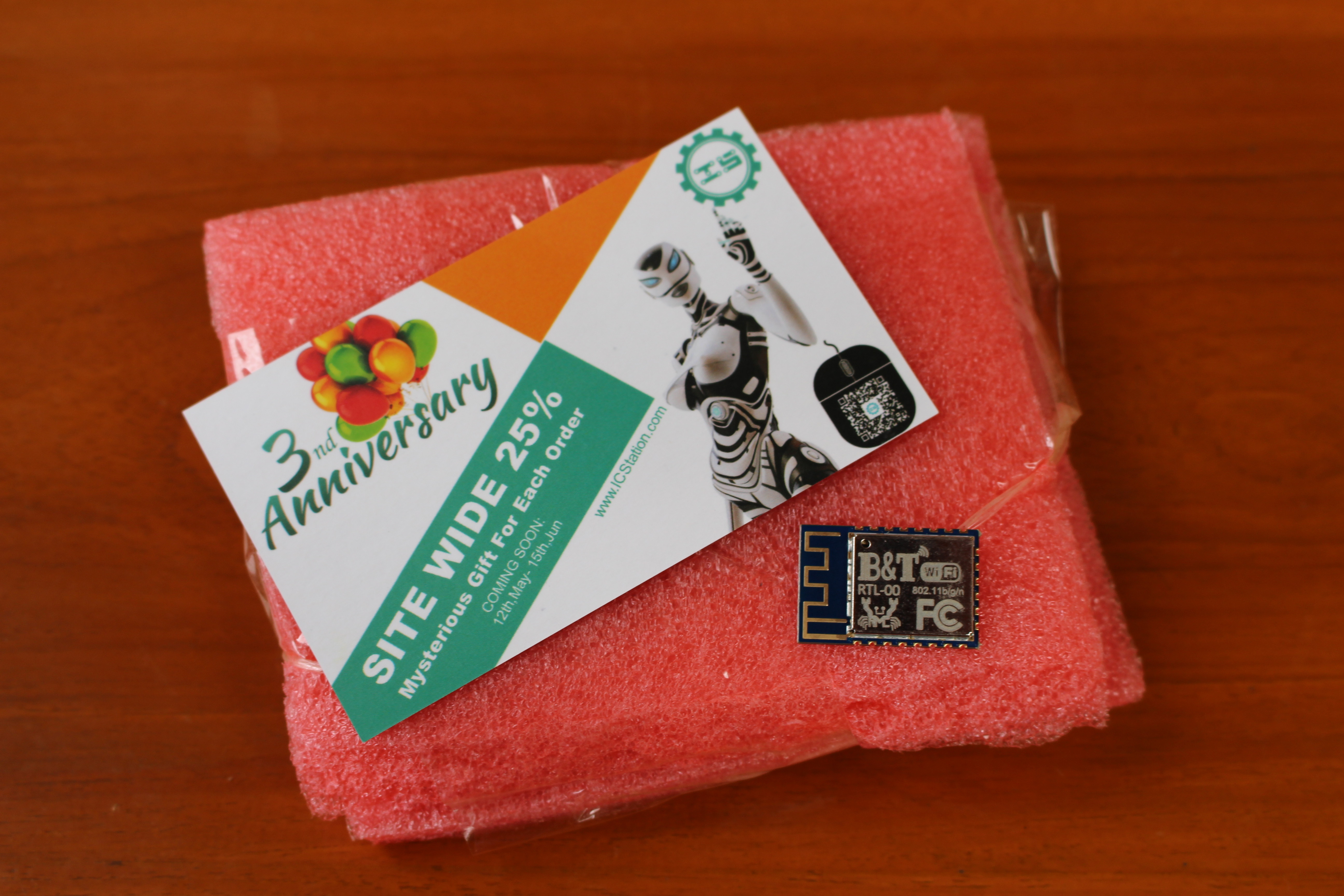
The announcement of the ultra-low cost ARM based Realtek RTL8710 WiFi modules for IoT applications generated quite a lot of buzz since they can potentially compete with the popular ESP8266 modules. The main problem at the time was documentation and software support, but after some searches we could find that RTL8710 was part of Realtek Ameba family, and found some documents and an SDK for RTL8710/RTL8711/RTL8195. ICStation also kindly provided one B&T RTL-00 module for review, which costs $3.55 shipped per unit, and as low as $2.85 if you purchase 10 or more.
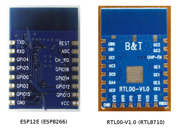
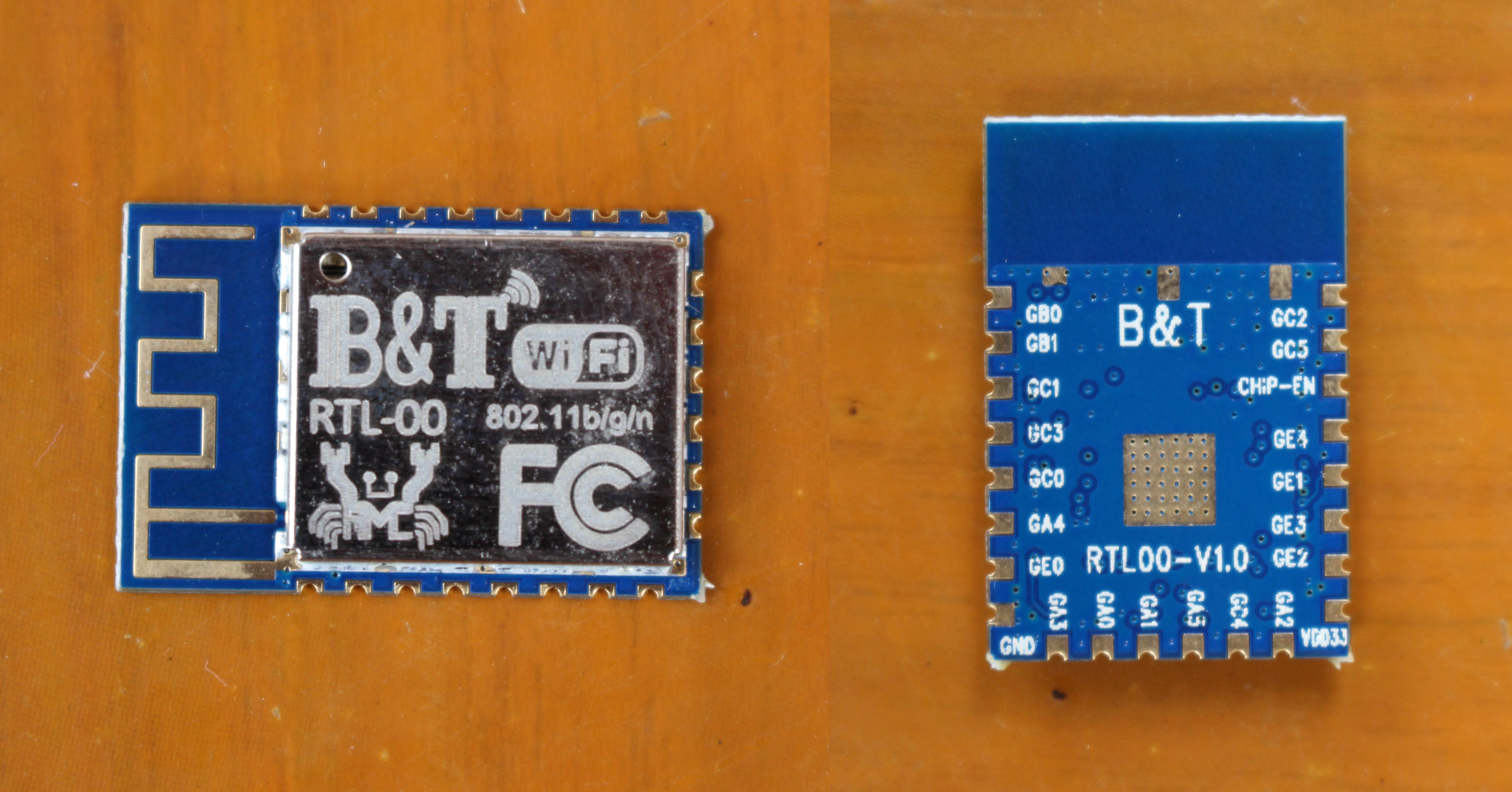
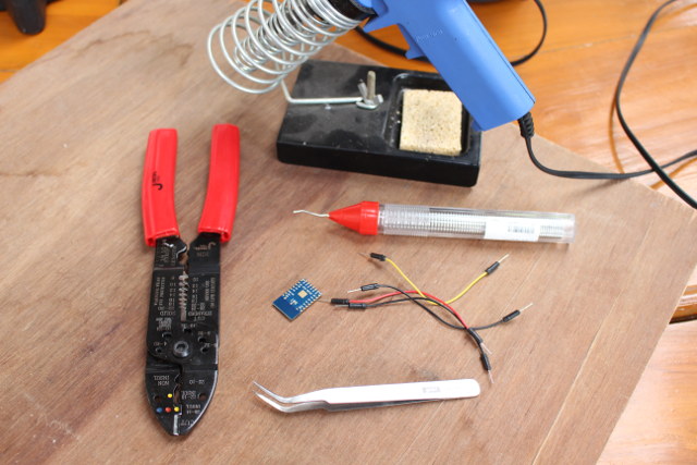
The question here is how to get started? The answer can be found in page 8 of the Chinese datasheet for the module with GB0 and GB1 pins used for Tx and Rx to access the serial console. Time for some soldering…
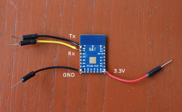
For the first test, we’ll just need Tx (GB1), Rx (GB0), GND and 3.3V, and cut breadboard wires to give me the flexibility to use it with a breadboard just in case.
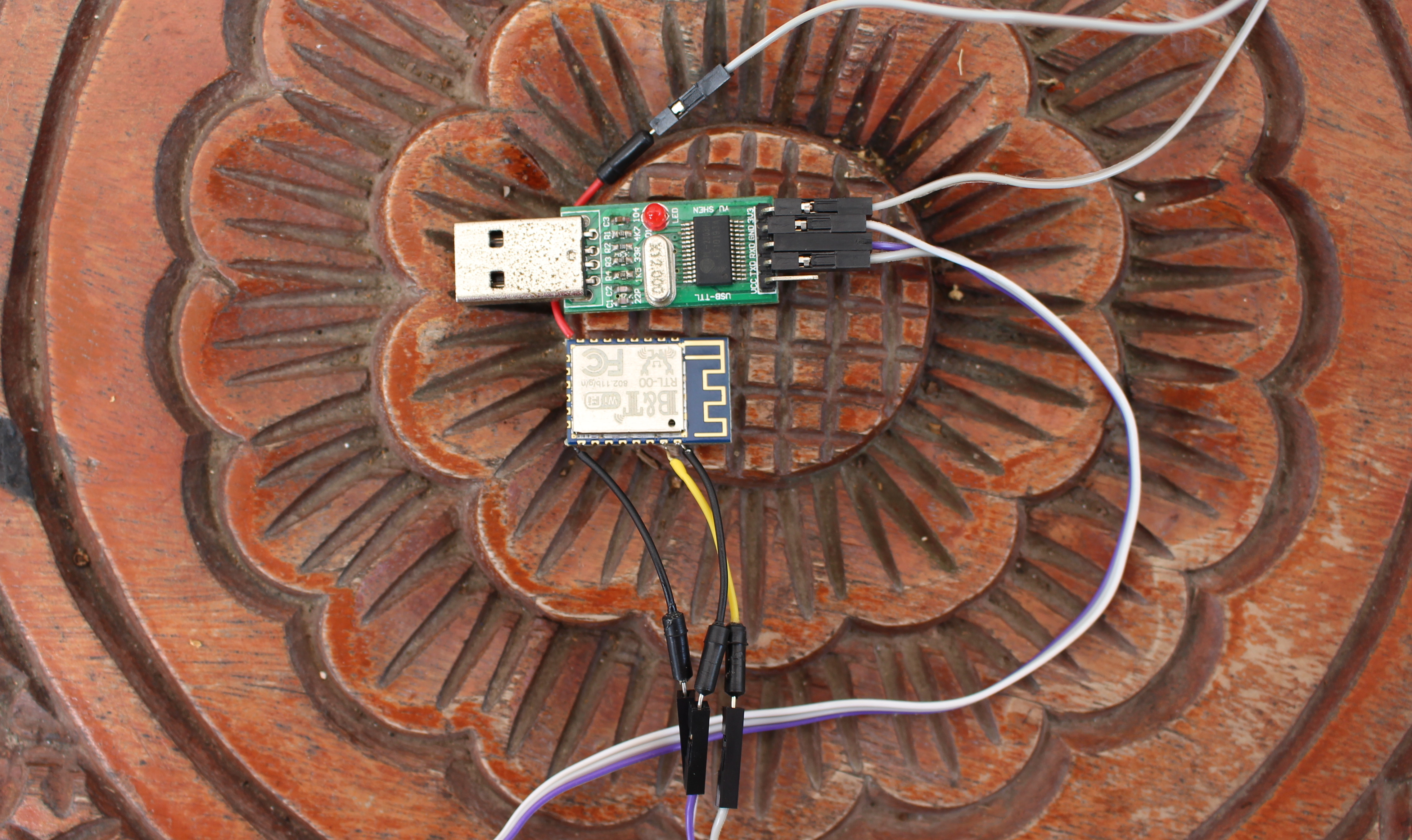
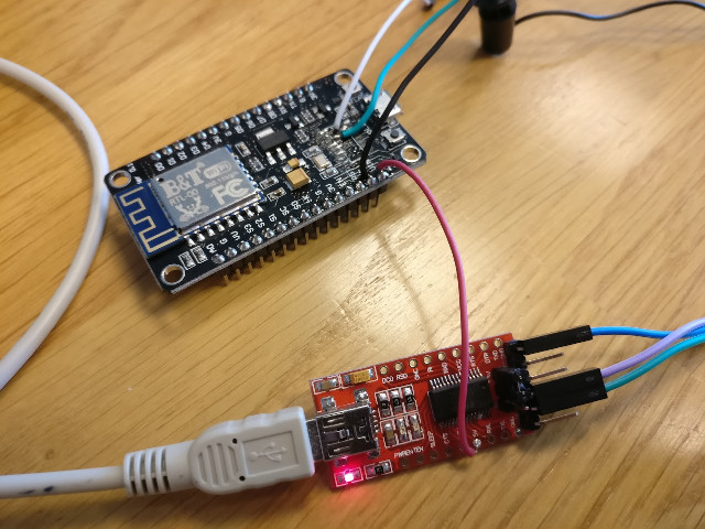
Now you need to connect the module to a USB to TTL debug board with all four pins connected since it will also provide power.
Insert the debug board into a USB port of your computer, and setup a serial connection @ 38400 8N1 using minicom, screen, putty, or other serial capable app. I struggled to get the full boot, until I found ATSR command would reboot the board:
1 2 3 4 5 6 7 8 9 10 11 12 13 14 15 16 17 18 19 20 21 22 23 24 25 26 27 28 29 30 31 32 33 34 35 36 37 38 39 40 41 42 43 44 45 46 47 48 49 50 51 |
[B&T_IOT_RTL8710]#ATSR ========================================================= ROM Version: 0.3 Build ToolChain Version: gcc version 4.8.3 (Realtek ASDK-4.8.3p1 Build 2003) ========================================================= Check boot type form eFuse SPI Initial Image1 length: 0x3704, Image Addr: 0x10000bc8 Image1 Validate OK, Going jump to Image1 ===== Enter Image 1 ==== load NEW fw 0 Flash Image2:Addr 0xb000, Len 321412, Load to SRAM 0x10006000 No Image3 Img2 Sign: RTKWin, InfaStart @ 0x10006079 ===== Enter Image 2 ==== [B&T_IOT_RTL8710] ###################### #################### ######################## [B&T_IOT_RTL8710] # # # # # # [B&T_IOT_RTL8710] # ################ # # # ################## ######### ######### [B&T_IOT_RTL8710] # # # # # # # # [B&T_IOT_RTL8710] # # # # # # # # [B&T_IOT_RTL8710] # # # # # # # # [B&T_IOT_RTL8710] # # # # # # # # [B&T_IOT_RTL8710] # ################ # # # # # [B&T_IOT_RTL8710] # # # # # # [B&T_IOT_RTL8710] # ################## # ####### # # # [B&T_IOT_RTL8710] # # # # # # # # [B&T_IOT_RTL8710] # # # # # ####### # #### # # [B&T_IOT_RTL8710] # # # # # # # # # # # # [B&T_IOT_RTL8710] # # # # # # # # # # # # [B&T_IOT_RTL8710] # # # # # # # # # # # # [B&T_IOT_RTL8710] # ################ # # ########## ##### # # # [B&T_IOT_RTL8710] # # # # # # [B&T_IOT_RTL8710] ####################### ##################### ######## [B&T_IOT_RTL8710] ######### Company website&Support&Forum link: http://www.iot-tech-now.com/ ############## [B&T_IOT_RTL8710] ######### CHECK FIREWARM SUCCESS !!! ############## [B&T_IOT_RTL8710]# Initializing WIFI ... Start LOG SERVICE MODE RTL8195A[HAL]: ISR 81 had been allocated!!! WIFI initialized init_thread(50), Available heap 0xb160 Enter INTERACTIVE MODE # |
If you type help you’ll see some AT commands:
1 2 3 4 5 6 7 8 9 10 11 12 13 14 15 16 17 18 19 20 21 22 |
[B&T_IOT_RTL8710]#help WLAN AT COMMAND SET: SET LOG OUTPUT MODE: 1. # ATSE=2(0: NO DEBUG,1:OUTPUT REMOTE UART, 2:LOCALE UART, DEFAULT MODE 1 ===========STA MODE================= 1. Wlan Scan for Network Access Point # ATWS 2. Set Wifi STA Mode # ATPW=1 3. Connect to an AES AP # ATPN=<ssid>,<pwd>,<key_id>(,<bssid>) ===========AP MODE================= 1. Set Wifi AP Mode # ATPW=2 2. Set AP parameter # ATPA=<ssid>,<pwd>,<chl>,<hidden> ===========TEST WIFI Status============== 5. View WIFI Status #ATW? 5. Ping #ATPP=xxxx.xxxx.xxxx.xxxx |
You can find the full AT command set in RTL8710 forums, and somehow it differs from the AT command set found in AN0025 Realtek at command.pdf application note available in Ameba Standard SDK.
Time to have some fun by trying to connect the board to my WiFi router:
1 2 3 4 5 6 7 8 9 10 11 12 13 14 15 16 17 18 19 20 21 22 23 24 25 26 27 28 29 30 31 32 33 34 35 36 37 38 |
# ATWS [ATWS]: _AT_WLAN_SCAN_ [MEM] After do cmd, available heap 41056 2 Infra 94:0c:6d:e6:5b:10 -42 1 6 WPA/WPA2 AES 4 Infra d0:c7:c0:f9:eb:0f -46 11 6 WPA/WPA2 AES [B&T_IOT_RTL8710]#ATPW=1 [MEM] After do cmd, available heap 45296 [B&T_IOT_RTL8710]#ATPN=CNX-TRANSLATION,somepasswordhere RTL8195A[Driver]: set ssid [CNX-TRANSLATION] RTL8195A[Driver]: start auth to 94:0c:6d:e6:5b:10 RTL8195A[Driver]: auth success, start assoc RTL8195A[Driver]: association success(res=5) RTL8195A[Driver]: set pairwise key to hw: alg:4(WEP40-1 WEP104-5 TKIP-2 AES-4) RTL8195A[Driver]: set group key to hw: alg:2(WEP40-1 WEP104-5 TKIP-2 AES-4) key1 IP address : 192.168.0.110 [MEM] After do cmd, available heap 45128 [B&T_IOT_RTL8710]#ping 192.168.0.1 [ping_test] PING 192.168.0.1 120(148) bytes of data [ping_test] 128 bytes from 192.168.0.1: icmp_seq=1 time=7 ms [ping_test] 128 bytes from 192.168.0.1: icmp_seq=2 time=4 ms [ping_test] 128 bytes from 192.168.0.1: icmp_seq=3 time=4 ms [MEM] After do cmd, available heap 45128 # |
Success, and that was easy. Now AP mode….
1 2 3 4 5 6 7 8 9 10 11 12 13 14 15 |
# ATPW=2 [MEM] After do cmd, available heap 45296 [B&T_IOT_RTL8710]#ATPA=CNXSOFTRTL8710,wifiiot2,3,0 Writting boot mode 0x77665502 and Wi-Fi setting to flash ... LwIP_DHCP: dhcp stop. Deinitializing WIFI ... WIFI deinitialized Initializing WIFI ... WIFI initialized [MEM] After do cmd, available heap 45104 |
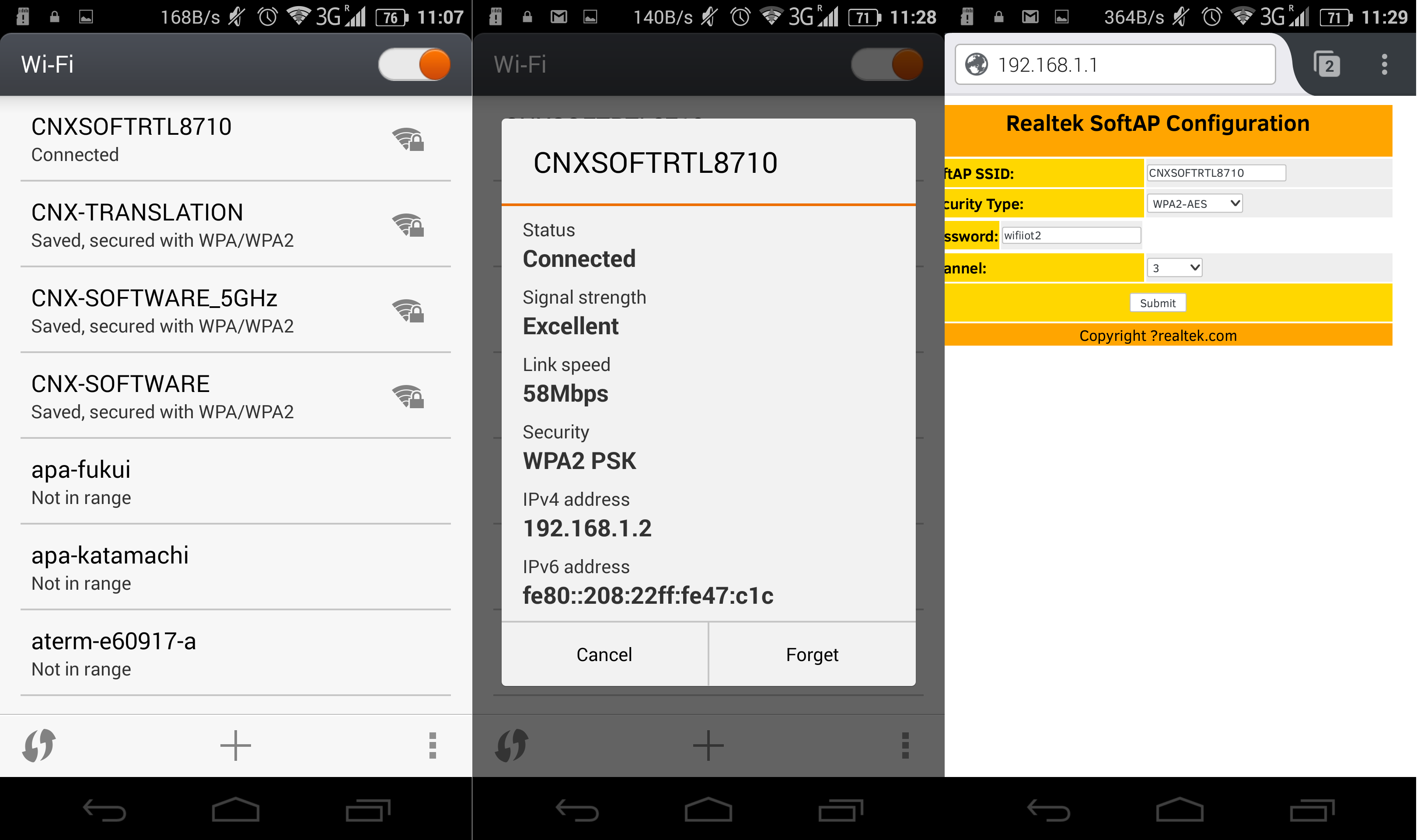
ATPA needs four arguments with ESSID,password (8 to 64 characters), channel, and hidden or not (1 or 0). I could now find the new access point with my phone, so I connected to it and typed the password. The serial console outputted the following during the connection:
1 2 3 4 5 6 7 8 9 10 11 12 13 14 15 16 17 18 |
[B&T_IOT_RTL8710]# RTL8195A[Driver]: +OnAuth: 00:08:22:47:0c:1c RTL8195A[Driver]: +OnAssocReq RTL8195A[Driver]: ap mode 4-1 RTL8195A[Driver]: ap mode 4-2 RTL8195A[Driver]: ap mode 4-3 RTL8195A[Driver]: ap mode 4-4 RTL8195A[Driver]: set pairwise key to hw: alg:4(WEP40-1 WEP104-5 TKIP-2 AES-4) c RTL8195A[Driver]: set group key to hw: alg:4(WEP40-1 WEP104-5 TKIP-2 AES-4) key1 [B&T_IOT_RTL8710]# |
The command ATW? will return lots of info about WiFi status:
1 2 3 4 5 6 7 8 9 10 11 12 13 14 15 16 17 18 19 20 21 22 23 24 25 26 27 28 29 30 31 32 33 34 35 36 37 38 39 40 41 42 43 44 45 46 47 48 49 |
[B&T_IOT_RTL8710]#ATW? [ATW?]: _AT_WLAN_INFO_ WIFI wlan0 Status: Running ============================== [rltk_wlan_statistic] tx stat: tx_packets=667, tx_dropped=0, tx_bytes=67662 [rltk_wlan_statistic] rx stat: rx_packets=2219, rx_dropped=2917, rx_bytes=266600 [rltk_wlan_statistic] min_free_heap_size=44000, current heap free size=44944 [rltk_wlan_statistic] max_skbbuf_used_num=4, skbbuf_used_num=0 [rltk_wlan_statistic] max_skbdata_used_num=4, skbdata_used_num=0 [rltk_wlan_statistic] max_timer_used_num=11 WIFI wlan0 Setting: ============================== MODE => AP SSID => CNXSOFTRTL8710 CHANNEL => 3 SECURITY => AES PASSWORD => wifiiot2 Interface (wlan0) ============================== MAC => 00:f8:87:11:00:12 IP => 192.168.43.1 GW => 192.168.43.1 Associated Client List: ============================== Client Num: 1 Client 1: MAC => 00:08:22:47:0c:1c Task List: log_servi R 5 776 6 IDLE R 0 42 4 Tmr Svc B 5 456 5 TCP_IP B 9 754 7 rtw_check B 5 220 30 rtw_recv_ B 5 994 25 interacti B 4 1132 16 LOGUART_T B 9 86 1 cmd_threa B 6 298 28 rtw_littl B 10 456 29 rtw_inter B 6 208 27 rtw_TDMA_ B 7 220 31 rtw_xmit_ B 5 178 26 [MEM] After do cmd, available heap 44944 |
I’ll complete those little tests by enabling the web server in the board:
1 2 3 4 5 6 7 8 9 10 11 12 13 14 15 16 17 18 19 20 21 22 23 24 25 26 27 28 29 30 31 32 33 34 35 36 37 38 39 40 41 |
# ATSW=c WEB:Enter start web server! [MEM] After do cmd, available heap 42672 LoadWifiConfig(): Read from FLASH! LoadWifiConfig(): local_config.boot_mode=0x77665502 LoadWifiConfig(): local_config.ssid=CNXSOFTRTL8710 LoadWifiConfig(): local_config.channel=3 LoadWifiConfig(): local_config.security_type=1 LoadWifiConfig(): local_config.password=wifiiot2 LwIP_DHCP: dhcp stop. Deinitializing WIFI ... WIFI deinitialized Initializing WIFI ... WIFI initialized RTL8195A[Driver]: +OnAuth: 00:08:22:47:0c:1c RTL8195A[Driver]: +OnAssocReq RTL8195A[Driver]: ap mode 4-1 RTL8195A[Driver]: ap mode 4-2 RTL8195A[Driver]: ap mode 4-3 RTL8195A[Driver]: ap mode 4-4 RTL8195A[Driver]: set pairwise key to hw: alg:4(WEP40-1 WEP104-5 TKIP-2 AES-4) c RTL8195A[Driver]: set group key to hw: alg:4(WEP40-1 WEP104-5 TKIP-2 AES-4) key1 [B&T_IOT_RTL8710]# |
You can now connect to the web interface to configure the access point.
AT commands are all good, and you can configure WiFi, UDP/TCP servers, and even OTA firmware update, but there’s nothing about controlling GPIOs there… So that will be something to look into. [Update: ATSG is the command for GPIOs. See comment]
Dpape on RTL8710 forums discovered something very interesting: B&T RTL-00 module is pin-to-pin compatible with ESP12E module based on ESP8266, so if you already own a board with such module including NodeMCU board, you could unsolder the ESP8266 module, and replace it with RTL8710 and get going.
That’s exactly what he’s done and shown to work, with the module bought from Aliexpress, which appears to come pre-loaded with the exact same firmware. You’d normally not need the red USB debug board as shown above, but he removed the USB to TTL chip on NodeMCU previously, so that’s why…
The modules are actually only mostly pin-to-pin compatible, as for example GC5, corresponding to ADC on ESP12E, does not seem to support ADC, but only I2C1 SCL, SPI0 CS2, and GPIO_INT signals. But the power signals, Tx and TX, and most GPIO signal will match.
Realtek RTL8710 is still nowhere near ESP8266 in terms of community and software support however. However an ARM development board company – previously featured in this blog and many news outlets – is involved in the project, and I’ve been informed more details will be provided in 2 to 3 weeks. The current modules sold are for the Chinese market, and an international version is planned with a slightly different radio.
Jean-Luc started CNX Software in 2010 as a part-time endeavor, before quitting his job as a software engineering manager, and starting to write daily news, and reviews full time later in 2011.
Support CNX Software! Donate via cryptocurrencies, become a Patron on Patreon, or purchase goods on Amazon or Aliexpress